
THE AURORA BOREALIS IS ONE OF nature's most spectacular nighttime displays. Shimmering curtains of green, white, and even red light dance in the northern skies. Visible effects of charged particles from the sun raining down on the Earth's ionosphere, northern lights or auroras, are visible in the northern night sky during high sunspot activity. The Aurora Australis, the southern hemi sphere's counterpart of the Aurora Borealis, can be seen at night by looking toward the south pole.
These displays of undulating light are formed when flares from the sun's surface (sun spots) launch showers of high energy ionized particles and X rays into space. Mostly electrons, the showers stream out from the sun and are attracted by the Earth's magnetosphere, an invisible magnetic field around the Earth.
Shaped like an pumpkin, the magnetosphere terminates at both magnetic poles but is many miles thick above the equator. Dimples at both poles form "sinks" that funnel the particles toward the poles where they ionize the gas in the ionosphere. Those collisions in duce the gases to emit their characteristic light wavelengths--as in neon signs and fluorescent lamps.
The charged particle bombardment of the magnetosphere initially compresses it, temporarily increasing the strength of the Earth's geomagnetic field. The aurora monitor described here is sensitive enough to detect changes in the field caused by those "magnetic storms." Thus it can indirectly sense sunspots and predict the presence of auroras in the night sky.
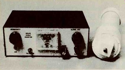
FIG. 1--THE TWO PARTS OF AURORA MONITOR are the control/display unit, left,
and the sensor head, right.
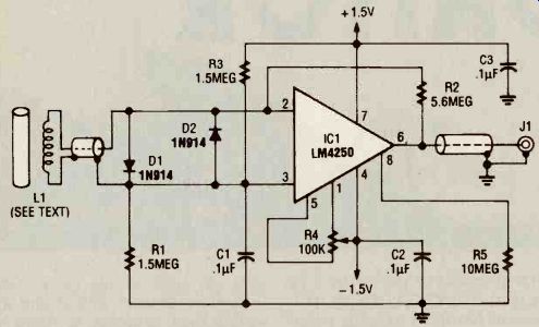
FIG. 2--SCHEMATIC FOR THE SENSOR HEAD circuit.
The monitor also senses changes or anomalies in the magnetic field caused by large metal objects such as cars or trucks moving near the monitor. This permits it to act as an intrusion detection monitor able to detect the approach of vehicles at night in restricted areas. The monitor can also detect the presence of permanent magnets (such as those in speakers), and stray fields from AC-power lines.
Early warning of auroras will both permit you to observe them in the night sky or use them for boosting the range of your amateur radio transmissions. Auroras and their accompanying magnetic storms generally block or scramble the lower radio frequencies, but the higher frequencies can over come this interference. Radio amateurs aim their antennas north during those storms, thus taking advantage of the phenomena to reach other hams on the opposite side of the Earth that could not be contacted during periods of low sunspot activity.
In addition to scrambling low-frequency radio communications, the magnetic storms caused by auroras can induce large currents in power trans mission lines. Those currents can cause overload, plunging large regions of the country into darkness. Auroras and related magnetic storms are quite common during the decreasing parts of the 11-year sunspot cycle such as the period we are now in.
Detecting magnetic activity.
Figure 1 shows the author's prototype Aurora Monitor. It is sensitive to a pulse of one ampere at distance of one meter, which corresponds to one milli-gauss. (The Earth's magnetic field is about 0.5 gauss.) The Aurora Monitor has two components-the sensing head and the control/display unit which are connected by a coaxial cable. The sensing head contains a sensing coil, a DC nano amplifier capable of current amplification of 500, and a separate power pack, all enclosed the tubular case shown on the right side of Fig. 1.
The control/display unit contains an active filter, additional amplification circuitry, a moving-coil ammeter, and an audio oscillator with speaker. Figure 1 shows the front-panel controls and indicators of the monitor: moving-coil ammeter, SENSITIVITY. RATE, and ALARM ADJUST potentiometers as well as power (oFF), filter-in and RANGE switches.
How the sensor head works Refer to the sensor circuit schematic, Fig. 2. Gain is provided by IC1. a National Semiconductor LM4250 programmable operational amplifier. It is protected from overvoltage and transients by diode D1 and D2, and its overall gain is set by resistors R1 and R2. The output of IC1 is driven to zero or balanced by network R3 and R4. Its output should remain at zero as long as no changes occur in the ambient magnetic field.
Bypass capacitors C2 and C3 are placed across the positive and negative power supply.
Power for the sensing amplifier is obtained from two C cells.
The circuit draws very little current. so it can be left on at all times-the reason why it has no power switch.
Control/display operation Refer to Fig. 3 for the schematic of the control/display circuit. It provides an additional gain of 200 over that of the sensor circuit. The control/display circuit includes an adjustable low-pass notch filter, IC2, a Lin ear Technology LTC1062. By adjusting the clock frequency of the filter with resistor R11 and the capacitors C4, C5, and C6, the filter cancels interference frequencies and noise in the 2-Hz to 10-kHz band. The notch filter can also screen out 60-Hz noise. Switch S2 inserts or removes the filter.
IC3, an LM201A general purpose op-amp, filters out the clock noise generated within the filter chip. The output of IC3 is fed into the non-inverting in put of IC4-a, half of a dual 747 general purpose op-amp. The overall gain of IC4-a is adjusted by resistor R16. 'Dimmer potentiometer R15 adjusts the offset or balance. PULSE SHAPE potentiometer R17 and capacitor C5 form an optional pulse-shaping network for coupling the Aurora Monitor to a chart recorder or an analog-to-digital conversion board of a personal computer.
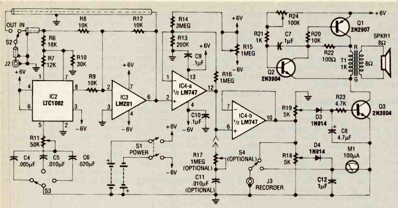
FIG. 3--SCHEMATIC FOR THE DISPLAY-ALARM circuit.
The output of IC4-a is coupled to a voltage follower at IC4-b.
The output of IC4-b is divided into two channels. One Channel is fed through 5000-ohm SENSITIVITY potentiometer R18, which adjusts the output level of the signal fed to the 100-microampere panel meter M1.
Movement of the meter's needle shows changes in the local magnetic field. Potentiometer R18 also adjusts the output signal that can be fed to a chart recorder for data logging.
The other channel is fed through ALARM ADJUST 5000-ohm potentiometer, R19, which sets the threshold or setpoint for the reflex oscillator circuit that follows it. The oscillator consists of transistors Q1, Q2, and Q3 and associated components. Speaker SPKR1 gives an audible indication of changes in the local magnetic field. The network of diode D3 and aluminum electrolytic capacitor C8 performs additional filtering for the input signal to the reflex oscillator section.
Transistor Q1 controls the audible alarm by clamping the negative voltage returning through the ground path. When a magnetic event occurs, the speaker emits an audible alarm, and the meter gives a visual indication of a changing magnetic field. The adjustment of ALARM ADJUST potentiometer R24 can remove distortion from the sound of the speaker.
The author's prototype control/display unit is powered by eight AA cells: four cells provide positive voltage and four cells provide negative voltage. As an alternative, the monitor can be powered by rechargeable nickel-cadmium cells.
Construction
Finished sensor and control/ display PC boards can be purchased from the source given in the Parts List. However, the circuit boards can be fabricated and drilled with the foil patterns included here. The outline dimensions of the author's prototype sensor board are 2 1/16 x by 2 9/16 so the smaller dimension can fit inside the pipe section used as the sensor head housing.
The outside dimensions of the control/display board in the prototype are 2 7/8 x 5 inches to fit inside the instrument case selected. Unless the completed board is purchased, holes must be drilled in the board for mounting transformer T1 and mounting the board in the instrument case.
The circuitry can also be built on standard punch board for point-to-point wiring. The out side dimensions of the circuit boards can be modified for packaging in the instrument and sensor head cases of your choice.
Sensor circuitry
Refer to sensor parts-placement diagram Fig. 4. It is recommended that all integrated circuits for this project be mounted in sockets. Position the socket for IC1 and all resistors, capacitors and diodes on the sensor board, paying attention to the polarity of the diodes. Solder all board-mounted components in position and trim excess leads. Set the sensor board aside and assemble and solder all board-mounted components to the control/display board.
Control/display circuitry
Refer to control/display placement diagram Fig. 5. Position the three sockets for IC's 2, 3 and 4, the three transistors Q1, Q2 and Q3 and all resistors, capacitors, diodes and board-mounted potentiometers as shown, making sure that the polarities of the diodes and the electrolytic capacitor are ob served. Solder all leads and trim them close to the PC board.
Verify the locations of the 1000-ohm and 8-ohm windings of transformer T1 and orient it as shown in Fig. 5. Insert the tabs of the transformer through the drilled holes and bend them to clamp the transformer to the board. Before soldering any transformer winding leads, check the windings with an ohmmeter. The reading across the 1000-ohm winding should measure in hundreds of ohms while that across the 8-ohm winding should be only a few ohms.
Solder all transformer windings to the correct board pads and cut a length of bare copper wire and solder it across both mounting tabs on the foil side of the board. Now complete the sensor-head assembly.
Winding the detection coil
The coil L1 in the sensor head detects changes in the local magnetic field. Wind approximately 10.000 to 15,000 turns of 28 AWG magnet wire over a soft iron core 1/2-inch in diameter and 12 inches long. (The iron core concentrates the flux lines by offering a lower reluctance path than air.) Coil impedance should measure from 200 to 300 ohms.
Wind the fine insulated magnet wire carefully on the iron core to avoid kinks and breakage. Tape the ends of the winding temporarily to the core and carefully solder hook-up wire at each end to form permanent terminals. The terminals can be secured to the core with room-temperature vulcanizing (RTV) adhesive to relieve any strains that might develop in the fine magnet wire.
Sensor-head housing
In the author's prototype. the sensing circuit board, coil, and battery pack are housed in a case made from standard 2 1 /16-inch inside diameter PVC water pipe cut to a length that will accommodate all of those elements as shown in Figs. 6 and 7.
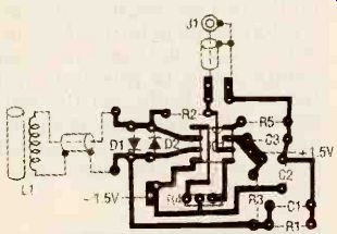
FIG. 4-PARTS ASSEMBLY DIAGRAM for the sensor head. Note that the coil L1
is a separate assembly wired to the circuit board. Refer to Fig. 7 for the
mechanical assembly.
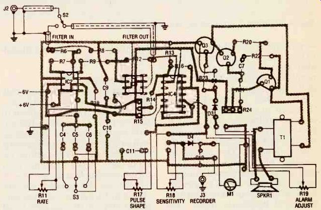
FIG. 5-PARTS ASSEMBLY DIAGRAM for the display-alarm unit. Note the panel-mounted
potentiometers, switches, meter and speaker.
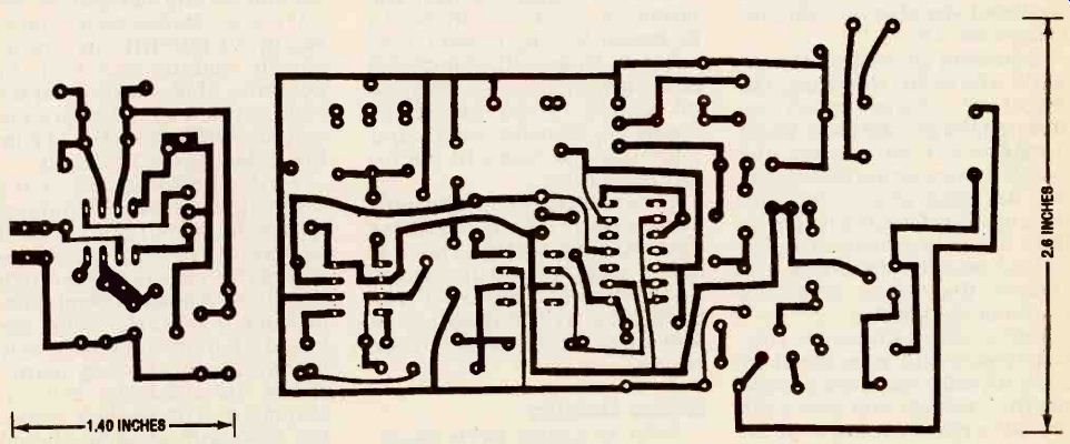
---------- FOIL SIDE OF SENSOR CIRCUIT board FOIL SIDE OF CONTROL-DISPLAY board
----------
PARTS LIST
All resistors are 1/4-watt, 5%, unless otherwise specified
R1, R3--1,500,000 ohms
R2--5,600,000 ohms
R4, R24--100,000 ohms, PCB trimmer potentiometer, carbon, Digi-Key CEG-15 or equivalent
R5--10,000,000 ohms
R6--18,000 ohms
R7--12,000 ohms
R8, R9--10,000 ohms
R10-30,000 ohms
R11-50,000 ohms, panel-mount potentiometer, Radio Shack No. 271-1716 or equivalent R12, R20-10,000 ohms
R13-200,000 ohms
R14-3,000,000 ohms
R15-1,000,000 ohms, PCB trimmer potentiometer, Digi-Key CDG-16 or equivalent
R16-1,000,000 ohms
R17-1,000,000 ohms, panel-mount potentiometer, carbon, Radio Shack No. 271-1714 or equivalent
R18, R19-panel-mount potentiometer 5,000 ohms, Radio Shack 271-1714 or equivalent
R21-1,000 ohms
R22-100 ohms, 1/2W, 5% R23-4,700 ohms
Capacitors:
C1, C2, C3, C7, C9, C10-0.1µF, 35-volt C4-0.005 µF, 25-volt C5, C11--0.010 µF, 25-volt C6-0.02 uF , 25-volt C5-0.010 uF, 25-volt C8-4.7µF, aluminum electrolytic, 25-volt
C12-1µF, 35-volt Semiconductors
Q1-2N2907, PNP transistor
Q2, Q3-2N3904, NPN transistor
IC1-LM4250 (National Semiconductor), programmable op-amp
IC2-LTC1062 (Linear Technology) active filter
IC3-LM201A (National Semiconductor) op-amp
IC4-LM747 (National Semiconductor) dual op-amp D1 to D4-1N914 diodes
Other Components
S1-DPDT toggle power switch, panel-mounted. Digi-Key No. or equivalent ON-OFF S2, S4-SPST toggle switches, panel mounted, Radio Shack No. 275-326 or equivalent S3-three-position rotary switch, break before make, panel-mounted M1-100-microampere moving-coil meter, GC (Rockford, IL) No. 20-1111 or equivalent SPKR1-8-ohm speaker, 2-inch diameter, Radio Shack No. 40-245 or equivalent T1-1000-ohm to 8-ohm trans former, Radio Shack No. 273-1380 or equivalent L1-sensing coil (See text) PL1 and PL2-plug, RCA-type, Radio Shack No. 274-339 or equivalent J1, J2, and J3-jack, RCA-type, Radio Shack No. 274-346 or equivalent Miscellaneous: PC boards for sensor and control-display, sockets for IC's (three 8-pin and one 14-pin DIP), Instrument case with removable cover (Radio Shack No. 270-274 or equivalent), PVC pipe with 21/16-inch I.D.(see text), two PVC end caps for 2 1/2-inch O.D. pipe (one plain, the other with a threaded end plug), two quad AA-cell holders, one dual C-cell holder, two C and eight AA alkaline cells, knobs for potentiometers and switches, RG-174 U coaxial cable (see text), spool of No. 28 AWG mag net wire, iron rod 1/2-inch O.D. 12 inches long, non-magnetic stainless steel self-tapping screws, hook-up wire, bare copper wire, solder, nuts, bolts, lockwashers, PVC adhesive, RTV adhesive, miscellaneous hardware.
Note: The following monitor parts are available from Tom L. Petruzzellis, 340 Torrance Ave., Vestal NY 13850: PC board only-$12.95 Kit of parts less cell holders, alkaline cells, cases, speaker--$59.95 Check, and money order accept ed. Please add $3.50 shipping and handling. New York State residents must add sales tax of county of residence.
--------------
The covers of the sensing head housing are PCV caps that press fit over the 2 1/4-inch outside diameter of the pipe. The upper cap is a simple cup, but the lower cap is a sleeve with a threaded insert at its end. Drill a hole in the square base of the threaded insert for jack J1 and fasten it with a ring nut. Then close the cover on the empty pipe and drill two pilot holes 180° apart in the sleeve for self-tapping screws to clamp the cap in position after the sensor head is assembled.
Cut about a 6-inch length of RG-174/U coaxial cable, strip both ends and solder the inner conductor of one end to the jack terminal and its shield to the jack lug. Solder the inner conductor and shield of the other end to the sensor circuit board as shown in the parts placement diagram Fig. 4.
Attach the coil to the sensor circuit board with about a 6-inch length of RG-174/U coaxial cable as shown. Connect the inner conductor to one terminal and the shield to the other as shown in Fig. 4, and solder both in position. The prototype includes a twin C-cell holder that, with cells in position, has a maximum width dimension of less than 2 inches permitting it to slide easily into the sensor head pipe section.
Cut three lengths of hook-up wire to extend the lengths of the positive, negative and ground leads of the battery pack. Solder one end of those wires to the holder leads and the other ends to the sensor circuit board as shown in Fig. 4.
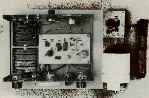
FIG. 6--AURORA MONITOR WITH HOUSING COVERS REMOVED showing internal arrangement
of circuit boards and panel mounted components. Control-display unit is
at left and sensor head is at right. Sensing coil L2 is at extreme right.
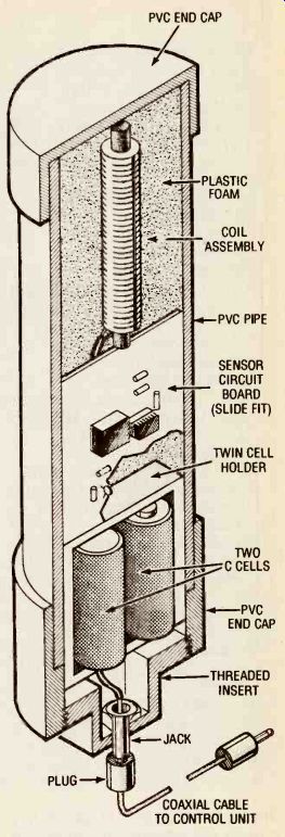
FIG. 7--MECHANICAL ASSEMBLY of sensor head. The coil is wrapped in polyurethane
foam and inserted into the case followed by the circuit board and the C-cell
holder. The lower cap is fastened to the pipe with non-magnetic self-tapping
screws.
Bond the upper cap to the PVC pipe section with PVC cement. Then position IC1 in its socket, making certain that pin 1 is located correctly as shown in Fig. 4. Finally, insert the C cells in the holder.
Wrap a layer of polyurethane foam around coil L1 to center it within the pipe section and insert both in the pipe section with the cover at the end. Then assemble the completed circuit board and battery pack to make sure that all of these parts will fit in the pipe section. Set the assembly aside until you are ready to perform the checkout steps.
Control/display unit
The control/display assembly is housed in a standard 7 x 5 x 3-inch aluminum electronics instrument case with a removable cover. Drill the holes in the front panel of the case for power ON Switch S1, FILTER IN Swath S2, RANGE switch S3 and (if used) optional recorder switch S4. Also drill the holes for SENSITIVITY, ALARM ADJ., arid RATE potentiometers (R18, R19, and R11 respectively). Cut out the hole for mounting meter M1.
Note: If you want to use the monitor strictly as a security monitoring system the meter can be omitted.
Fig. 5, allowing sufficient lengths to permit unimpeded circuit board assembly. Drill the holes in the back panel for jacks J2 and J3, and PULSE SHAPE potentiometer R17. Drill a series of holes in a circular pattern for the speaker SPKR1. Drill holes in the bottom of the case for mounting the control/display circuit board and two quad AA cell Assemble the panel-mounted switches, jacks, potentiometers, meter and speaker to the front and back panels of the case as shown in Fig. 6. (You might prefer to bond the face of the speaker to the inside of the back panel with RTV adhesive rather than bolts and nuts.) Determine the length of speaker wires needed to permit assembly of the circuit board in the instrument case, cut the wires to length and solder them to the board. Cut and solder all leads from panel-mounted components to the circuit board as shown in yet not allowing too much slack.
--------------
REFERENCES
1. Akasofu, S.I., "The Dynamic Aurora," Scientific American, May 1989
2. Amslie, A.G., "Explosions in the Solar Atmosphere," Astronomy Now, November 1987
3. Bone, N. "The Aurora," Astronomy Now February 1988
4. Foukal, P.V, "The Variable Sun," Scientific American, February 1990
5. Jones, E.W. Jr., "The Earths Magnetotail." Scientific American, March 1986
----------------
Cut about a 6-inch length of RG-174/U coaxial cable to connect INPUT jack J2 and the FILTER IN switch S2 and two other long to connect S2 to the FILTER-IN and FILTER-OUT pads on the control/ display board as shown in Fig. 5. Strip all cable ends and solder and trim all connections.
Assemble the control/display board to the base of the case with screws and 1/2-inch insulating standoffs, lockwashers and nuts. Bolt the two quad AA cell holders to the base of the case as shown in Fig. 6.Position the IC's in their sockets on the control-display board, making sure that all pin l's are in their correct positions. Insert the eight AA cells in the spring-loaded holders, observing the correct polarity.
Cut a length of RG-174/U coaxial cable to the length that will suit your installation (up to 20 feet). Strip the wire ends and attach phono plugs PL1 and PL2 to cable ends and solder or crimp them in position.
Ma and checkout 1st the sensing circuit first.
Connect a general purpose oscilloscope or multimeter to the output of IC1. Position a permanent magnet near coil L1 and the oscilloscope display should show a pronounced pulse. If a multimeter is used, its readout should jump.
Next, move L1 away from the magnet and the reading on the multimeter should fall to zero. If the reading does not go to zero, adjust trimmer potentiometer R4 in the sensor circuit. When the sensing head is adjusted and working correctly, close the lower cap and fasten it with two non-magnetic stainless steel self-tapping screws to complete the assembly. Connect one end of the plug-terminated coaxial cable to the sensor head jack 1 and the other end to the control/ display unit jack J2.
Turn on the power toggle switch of the control/display unit and turn SENSITIVITY potentiometer R18 full clock wise. The meter should remain at zero. Rotate ALARM ADJUST potentiometer R19 clockwise until the alarm just begins to sound. Then turn it back slightly so that no sound is heard to obtain the maximum sensitivity setting. Next, turn potentiometer R19 full clockwise.
There should be no sound from the speaker.
Position a small magnet or piece of metal next to coil L1, in the sensor head and the unit should now be activated: the speaker should emit sound, and the meter should read full scale. If everything checks out, you can now start observing magnetic field disturbances or anomalies.
Operating the monitor
In a quiet magnetic environment it might be necessary to adjust potentiometer R4 in the sensor head to the threshold of the meter movement. This fine adjustment eliminates any small dead zones in sensitivity.
Test the instrument's ability to detect the Earth's magnetic field by rotating the sensing head with short, quick, snapping motions in a counter-clockwise direction.
The Meter movement should jump off scale.
As rotation is continued, a direction will be found where the meter will have its lowest response. This nulling point is the north-south direction. Any objects containing permanent magnets such as speakers or meters that are brought into close proximity to the Aurora Monitor's sensing head coil L1 will affect the accuracy of the instrument's readings.
The Aurora Monitor can be connected to a chart recorder or it can pass signals to a personal computer with an analog-to-digital converter board. The recorder or PC can collect data for the study of magnetic fields, magnetic storms, and sunspot activity over long periods of time for further analysis. A set of high-impedance (greater than 1 kilohm) headphones can be plugged into jack J3 if you wish to "hear" the changes in magnetic fields.
If you want a permanent installation, mount the sensing head assembly so that it is directed away from any large met al obstructions, oriented on a north-south axis, and pointed slightly upwards. It's a good idea to fasten it to a heavy wooden post to prevent wind-induced vibrations.
------------------
Also see: