AMAZON multi-meters discounts AMAZON oscilloscope discounts
THE CHASSIS of your projects is as important to the operation of the equipment as is the electronic wiring. An improperly designed or badly constructed chassis may have a great effect on the operation and useful life of the equipment.
There are two basic chassis types used by the home experimenter, the perforated phenolic board, which is shown in Fig. 39, and the aluminum chassis. The latter can be purchased as a blank box in radio supply shops or can be made from flat aluminum sheet by the builder.
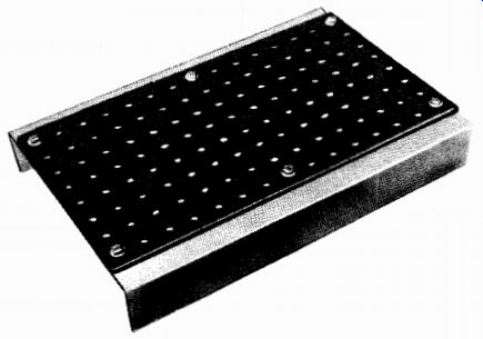
Fig. 39--Perforated phenolic board chassis.
The perforated board is suitable for mounting lightweight components such as transistors or miniature tubes. It is not sturdy enough for use with large transformers for power supplies or output stages.
Many experimenters like the phenolic board because it cuts mechanical work to a minimum. The only tools required are a sharp knife and a reamer or round file. With the exception of tube and transistor sockets and potentiometers, most parts can be mounted without tools. For example, to mount a resistor bend the leads, at an angle to the body and insert them through two convenient holes in the chassis, as shown in Fig. 40. A slight bend in the leads will hold the part in place until it is soldered. The stiffness of the leads and the soldered joint will hold light parts in place without trouble. Small transformers and variable capacitors can be screw mounted on the boards by using 6/32 or 4/32 screws. If none of the predrilled holes on the board line up with the mounting holes of the parts, it is a simple matter to drill holes where desired with a hand drill, the tip of a knife blade, or an awl.
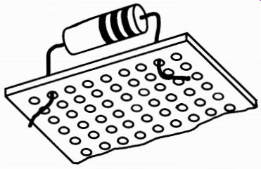
Fig. 40--Resistor mounted on chassis board.
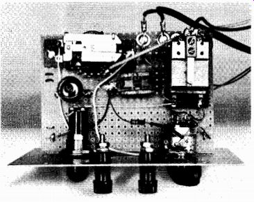
Fig. 41--Complete project wired on phenolic board.
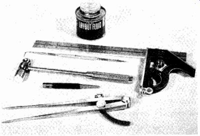
Fig. 42--Tools for chassis layout.
The aluminum chassis requires more working tools than the phenolic board chassis, but it is the only really satisfactory way to mount components in a large project. Some experimenters combine the advantages of the rigidity of an aluminum chassis with the working ease of the perforated board by mounting all of the larger components on an aluminum chassis and wiring the smaller components on a phenolic board. A space is then cut out on the aluminum chassis to fit the board and the board is mounted with a couple of screws. Finally, the wiring between the board-mounted components and those on the aluminum chassis is completed.
Although blank chassis bases are available in steel, it is better to use aluminum because it is an easy material to work and can be drilled, punched, and bent with ordinary hand tools. The one disadvantage of aluminum is that it is not easy to solder without special equipment.
However, this is not a serious drawback because a terminal strip, with a ground lug that can be bolted to the chassis, will provide a base to which all grounds can be soldered.
When working with a blank chassis, first prepare a layout showing the location and size of every hole to be punched or drilled on the chassis. This layout must then be transferred to the chassis itself before the work can be started. In some cases, you will be able to follow a chassis layout diagram that is part of the project. In other cases, you will have to prepare your own layout from scratch or by following the parts placement in photographs of the completed project.
The first step in laying out a chassis is to determine the parts' positions by arranging all of the major parts, including tube sockets, on top of the blank chassis. After you have done this, move the parts around until the most desirable arrangement is found.
Certain rules should be followed when laying out a chassis in this manner. First, care should be taken not to crowd large tubes (such as rectifiers and power amplifiers) near electrolytic capacitors or wax impregnated coils because excessive heat may easily damage these components. Tube sockets should be arranged to provide reasonably short connections between stages, but the input and output of amplifiers should be kept well separated.
Power transformers, filter chokes, and output transformers should not be bunched together at one end of the chassis. Keep them spread evenly across the chassis in order to distribute the weight of the equipment.
Visualize where volume controls, switches, pilot lights, etc., will be mounted on the front edge of the chassis and be certain to allow enough space. Too often a builder prepares a nice-looking layout only to find that a multi-laver rotary switch falls right over a tube socket, making the unit difficult to wire.
Laying Out the Chassis
When you have the parts in approximate position on the chassis.
make a full-size drawing of the chassis top on a sheet of paper. Now mark in the locations of the parts, taking all of your measurements from one edge of the chassis. Measure the distance between mounting holes on the parts and indicate these on the paper. Now you are ready to go to work on the chassis.
The basic tools required for laying out the chassis include a pair of dividers, a center punch, a small hammer, a scriber, and a combination square or ruler. Not all of these items are essential, but if all are available you will save time and trouble.
Select one corner of the chassis as your measuring base. Make all of your top-of-chassis measurements from the two sides comprising this corner. Now draw center lines for the various holes directly on the chassis, using the scriber and ruler as shown in Fig. 43. (Note how the layout fluid makes the lines stand out.) Use only enough pressure on the scriber to make a visible line on the surface of the metal.
When a single dimension is to be repeated a number of times, the divider can be set to this measurement and used to mark off all similar dimensions. The final step is to carefully center-punch all holes to be drilled.
Hold the center punch firmly at the point to be marked and tap it lightly with a hammer. Use only enough force to make a distinct mark on the metal. Too hard a blow will cause a large dent and may deform the chassis. A block of wood placed under the chassis while center-punching will prevent bending of the chassis (see Fig. 44).
With the chassis laid out, the next step is to drill the holes for the components. Because aluminum is a fairly easy material to work, practically all of the drilling and cutting can be done with ordinary hand tools. However, there are some additional tools that will make the whole job easier. You should have a drill (electric, if possible), a set of drill bits, a hammer, a half round, and a flat file. A fly-cutter, hole saw, or chassis punch is also a good investment. These tools can be used to make large holes for tube sockets and transformers. Although you can make holes for tube sockets with a drill and filing, a punch or cutter will save considerable muscle power. A fly-cutter is a pointed bar that fits into the chuck of a hand drill. An adjustable arm with a cutter blade can be set for any diameter hole. These cutters are available with square shanks for use with a hand brace or with round shanks for power drills.
Because the cutter is adjustable, you will need only one to handle al most all of your work.
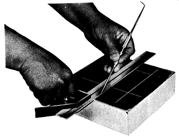
Fig. 43
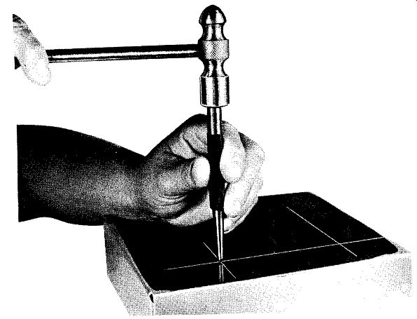
Fig. 44
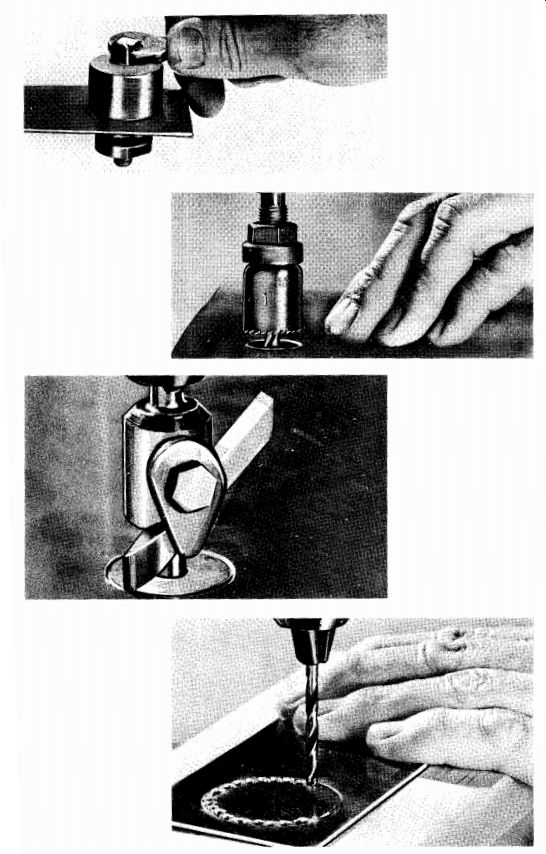
Fig. 45--Four ways to drill large holes.
The chassis punch is easier to use than the fly-cutter, but it is not adjustable. You will need a separate punch for each size hole. To use a chassis punch, drill a small pilot hole at the center of the larger hole to be cut, attach the base of the punch to one side of the hole and the cutter to the other, then tighten the screw. The screw pulls the base and punch together, cutting the metal between them. The result is a perfectly clean hole. These punches come in a wide variety of sizes, including square shapes for making transformer mounting holes and windows.
The hole saw is actually a hack-saw blade mounted around a drill that is used as a centering guide. Hole saws are not adjustable. They usually come with a set of cutters that will handle the most common hole sizes.
If you don't have the money available to purchase the special hole cutters described here, there is a simple method that can give you as good results with a bit more work. The procedure is as follows:
Use a compass to mark the size hole required on the chassis. Then make another circle that is smaller than the first by the radius of the drill you are going to use. For instance, to make a 1-inch hole draw a circle 1 inch in diameter. If you are going to use a 1/2-inch drill, make the second circle so that it will be 1/16 inch smaller than the outer circle. With a center punch, mark points around the inner circle, about 1/2 inch apart, and drill through each point. Now, with a small coping saw, cut around the circle connecting the holes together. The job is finished with a file. Clean away all of the high spots around the edge of the hole and shape it to the proper size.
Making a Chassis from Scratch
Thus far we have talked about planning and laying out our equipment on commercially available aluminum chassis. This is, by far, the easiest way; but it is expensive, and our layouts are limited to what ever shape and size chassis are available. Chassis can also be made from aluminum stock, at low cost and with a minimum of special tools.
Use 24-gage aluminum, which is available at most hardware stores. This gage material can be bent to form with only hand pressure, but will make a chassis sufficiently sturdy for almost any experimental application.
There are two construction steps. First a top plate is cut to size, then four side pieces are bent to shape and bolted to the top plate. The side members can be formed using two pieces of wood. The metal is clamped between the two strips of wood and bent to shape on a flat surface (see Fig. 46). Alternative chassis arrangements are shown in Fig. 47. These can be cut from one piece of 24-gage stock and bent to shape over a sharp edge such as a table or vise. Figs. 48-53 show materials from which chassis can be made.
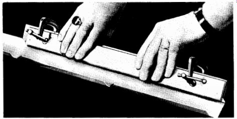
Fig. 46A-Bending sides of aluminum for chassis.
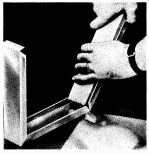
Fig. 46B-Bending aluminum with notches for desired chassis height.
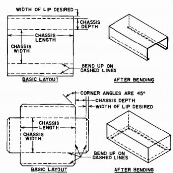
Fig. 47-Alternative chassis arrangements. Upper shows layout for chamele-type
chassis. Lower shows box-type layout.
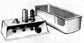
Fig. 48-Household pans used for chassis bases.
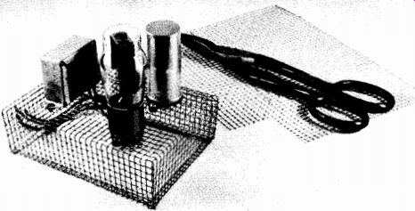
Fig. 49-Hardware cloth cut with metal shears and shaped to form a chassis.
Corners are held together by soldering or by wrapping ends of wire mesh together.
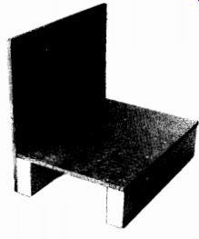
Fig.50--Masonite used for both chassis and front panels where shielding is
not critical.
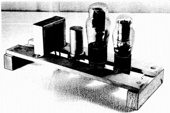
Fig. 51--Scraps of wood used to make a chassis base.
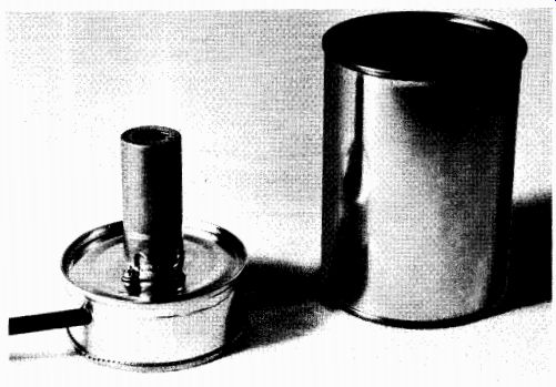
Fig. 52--A discarded tin can makes a good chassis base for one-tube circuits.
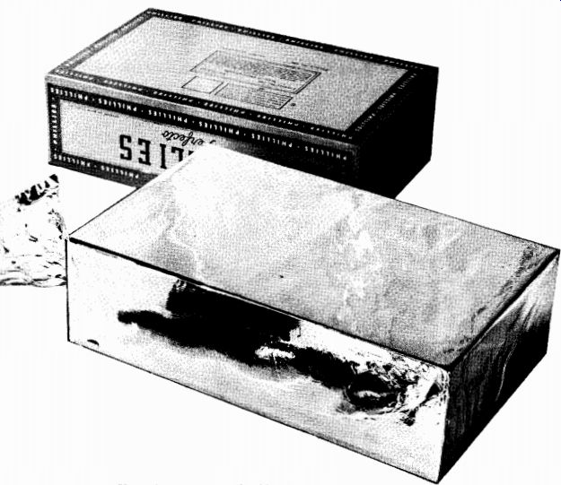
Fig. 53--A cigar box covered with aluminum foil makes a good shielded chassis.
Dressing Up a Chassis
Although the chassis on most projects will be hidden from view, the front control panel is there for everyone to see. There are two ways to make the panel professional-looking: First, sanitizing; second, the application of decals. The soft satin appearance of commercial equipment is not a secret process and is easily duplicated in the home shop by the use of chemicals obtained from commercial chemical shops.
Clean the aluminum with paint thinner to allow proper action of etching chemicals. Then dip it into a solution of warm water and sodium hydroxide or Okite No. 160. The aluminum will start to bubble.
After a few minutes wash it in water, then dip it into a solution of sodium dichromate. This last dipping will remove any black stains that may have appeared.
Photo-developing trays can be used for dipping small plates or chassis subpanels, provided that the solutions are not left in the trays for a long period. Two cautions in using this technique: Work in a well-ventilated room and use tongs to handle the parts. Hydrogen gas fumes are given off during the etching process, and ventilation will prevent them from accumulating in the room. The tongs will prevent caustic solutions from burning your skin.
A simpler method of finishing a panel is to use crackle finish paints available from parts houses. When applied to the surface, these paints dry to a rough finish similar to that on many professional pieces of equipment. They are available in handy spray cans.
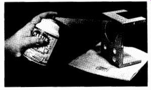
Fig. 54-Decals installed on panel front.
Decals are available in many forms to label the various switches and controls on your project. They are easy to install, and provide a useful purpose as well as a professional-looking appearance. Cut out the desired lettering, soak it in water, and then apply it to the wet surface of the panel. Next, smooth out any air bubbles that may be trapped under the decal and let it dry. Spray two coats of plastic over the surface after it has dried thoroughly. The decals will then be in place permanently (see Fig. 54).