AMAZON multi-meters discounts AMAZON oscilloscope discounts
FOR THE true experimenter, the kitchen table may serve as an adequate workbench. He can put up with the moving of unfinished projects when dinnertime comes. He can also put up with the hunt for parts lost in the movement. However, it is not necessary for the home experimenter to be with out a place to work. Even in a small apartment, it is possible to set up a workshop that will provide the features necessary to make your hobby a pleasure instead of a burden to everyone else in the house.
The ideal workbench should have several features. Some are essential, others are desirable, some are luxuries. Here is a checklist for your own work area:
1. Good lighting
2. Sufficient bench space
3. Main tools and instruments within easy reach but out of the way when not needed
4. Storage space within easy reach for commonly used parts
5. Additional storage space for larger parts and parts used less frequently.
If you have no space at all, a portable shop can be made that will fit into a closet when not in use. The man with a bit more room can build a shop that hangs on a wall, out of the way until needed. If the space is available, a permanent shop can be constructed at small cost.
None of the benches described below require any woodworking tools other than a screwdriver and a drill. If you take the parts list and diagram to your local lumberyard, you can have the pieces cut to size.
All you will have to do will be to screw them together.
Apartment Workshop
The experimenter living in an apartment needs a bench that can be put out of the way when it is not being used, but that will provide sufficient "elbow room" for his work. The solution to this problem is a wall unit with a drop-leaf "door" (see Fig. 67). When the door is open, a Masonite work surface is revealed which can stand plenty of abuse from soldering irons and tools. The front of the door has a small 3/4-inch flange into which an aluminum leg is fitted for support. Test equipment can be stored on the bottom shelf.
The second shell has enough room for twenty-four parts drawers in which to store resistors, capacitors, hardware, and miscellaneous items.
The third shelf will hold copies of books, schematics, and catalogues.
At the top is an adjustable shelf that will be handy for storing larger tools and projects. The adjustment feature can be installed with commercially available shelf supports.
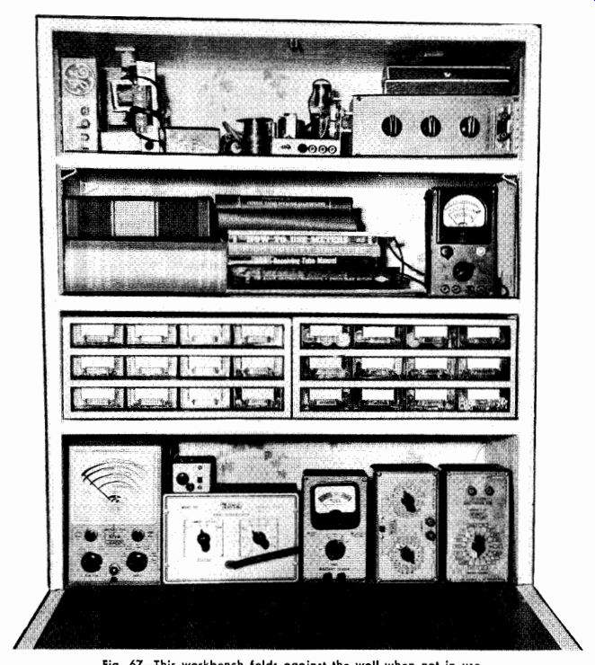
Fig. 67-This workbench folds against the wall when not in use.
Storage space is adequate for essential equipment.
Comparatively simple to put together, the unit should take only three or four hours to construct. The entire cabinet is made of 3/4-inch by 9 3/4-inch pine shelving * and is assembled with nails (8d or 10d size) and wood glue. The drop-leaf door is 3/4-inch plywood.
When the door is closed, it is held tight by a hook-and-eye catch.
Brass hinges (2 inches by 1/2 inch) are screwed to the front of the bottom shelf so that the door will close flush with the shelf. A 1/2-inch piece of tempered Masonite, glued to the back of the door, will serve as the work surface.
PARTS LIST
2—31 3/4" lengths of 3/4" X 9 3/4" pine shelving (sides of cabinet)
5--25" lengths of 3/4" X 9 3/4" pine shelving (top, bottom and shelves)
1--26 1/2" X 31 3/4" section of 3/4" plywood (front)
1-24 1/2" X 30" section of 1/2" tempered Masonite Misc. hook and eye, wood screws, nails, 2" X 1/2" hinges, etc.
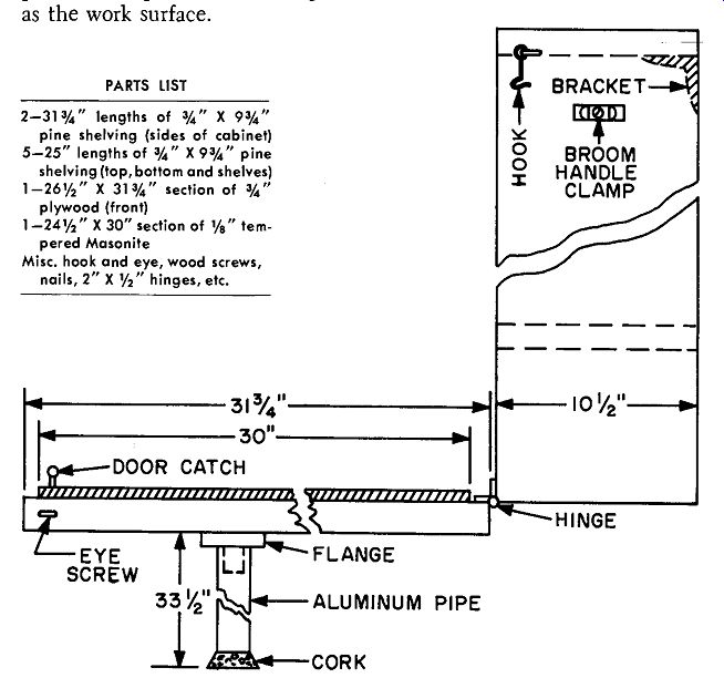
Fig. 68--Mechanical drawing of the "hidden" bench.
A 3/4-inch flange, into which an aluminum pipe can be inserted, can be mounted on the front panel. The pipe shown was cut from a discarded antenna mast and a cork was set in one end of it to prevent marring the floor. When not in use, the pipe can be stored on the side of the unit and held there by a broom-handle clip. You can determine the exact length of pipe needed after mounting the cabinet on the wall.
This board is sold as 1-inch by 10-inch shelving at lumber yards.
The cabinet is held in place on the wall by means of brackets and rawl plugs and screws, Moly or toggle bolts. The type of fastener used will depend upon the type of kitchen wall you have. If in doubt, consult your landlord or superintendent.
As a finishing touch, the outside of the cabinet can be covered with wallpaper or painted to match the wall.
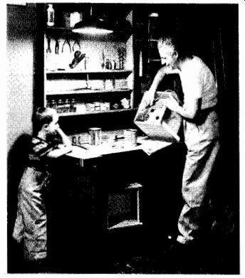
Fig. 69-Large workbench provides complete facilities for experimenter.
Note large storage area beneath bench.

---------
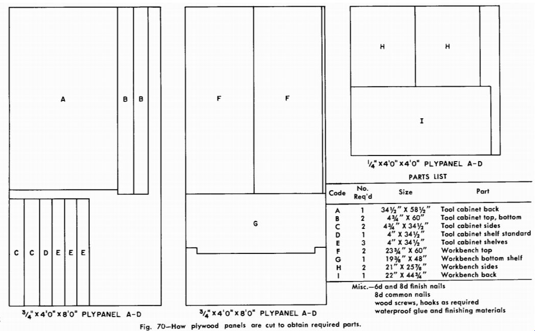
Fig. 70
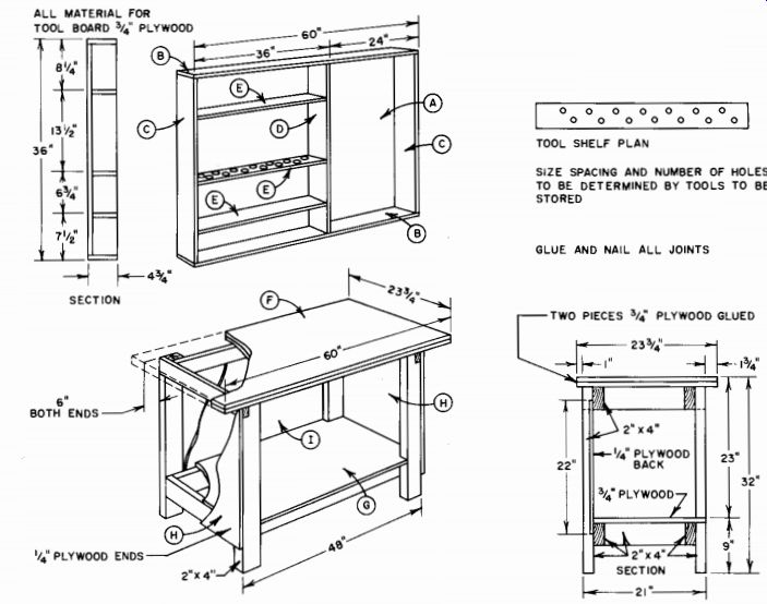
Fig. 71--Assembly drawing of workbench shows positions of all parts. Shelf
area can be arranged to suit your equipment.
Full-size Workshop
The bench shown in Fig. 69 will provide plenty of working and storage space for the experimenter with a basement or workroom at his disposal. A wall cabinet provides space for instruments and tools, and an additional space under the bench provides storage for heavy chassis and the "junkbox" for used parts. The entire setup can be constructed from two 4-foot by 8-foot plywood panels and one 4-foot by 4-foot 1/4-inch panel. The legs and cross braces are cut from 2-inch by 4-inch boards. All of the panels are 3/4 inch thick to ensure rigid construction.
Fig. 70 shows how the parts for the bench should be cut from the panels. Your local lumber dealer can do this cutting for you if you do not have the woodworking equipment. (Be sure to have the legs notched as indicated.) After the parts have been cut from the plywood panels, sandpaper all the edges, using 1/0 sandpaper. To assemble the 2 X 4 lower shelf framing use screws and glue on each joint. Screws can be 1 1/2-inch No. 8 flathead screws throughout the construction. Always pre-drill pilot holes for screws. Fasten the 3/4-inch plywood shelf to this frame. Then set up legs, end cross braces, and the top rails. Screw and glue the 1/4-inch plywood back panel and end panel to the 2 X 4's.
The top of the workbench is made from two 3/4-inch plywood panels glued together for rigidity. Coat one face of a panel with glue and place the other one on top of it. Install screws around the edges of the panels to hold them together. Place some screws around the center of the panels to hold that area in tight contact until the glue dries.
Install all of these screws from the side of the double panel that will be the bottom side of the bench top. Round off the edges of the top and corners with sandpaper and fasten the top to the framework with glue and screws.
To assemble the tool cabinet, glue and screw the side and end strips to the back panel. Bore holes for your tools in one shelf before installing the vertical divider and shelving. The shelves can be installed at any spacing that is suitable to your equipment. Typical spacings are given in the diagram.
Painting the understructure of the bench and tool cabinet gives worthwhile protection and makes cleaning easier. Rub it with 3/0 sand paper, prime the wood with enamel undercoating or resin sealer, and apply two finishing coats of paint in the color you desire.
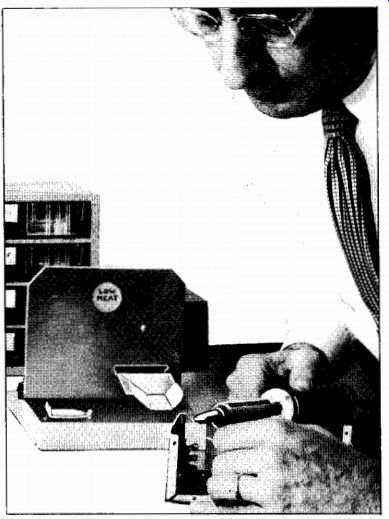
Fig. 72-Heat-controlled soldering stand keeps iron at low heat when not in
use.
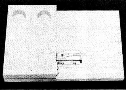
Fig. 73-Base block glued to main base. The two holes are 1 1/4 inches in diameter
and must line up with holes in aluminum plate.
Lever switch and bracket nestle in cutout made in main base and are secured in place with wood screws.
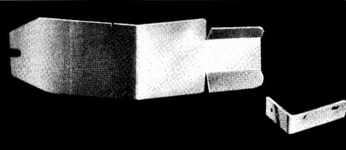
Fig. 74-Rocker fashioned from aluminum. Notches must fit snugly into narrower
part of rocker cutout in aluminum mounting frame.
The leaf spring is stainless steel strap and the switch bracket is aluminum.
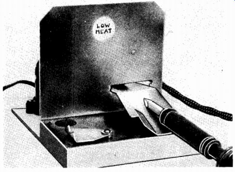
Fig. 75--Vertical section is aluminum; it is bent where it joins base block.
Slit in lower right corner accommodates rocker-arm rest. Two circular holes
must be punched in aluminum to match holes for cleaner and rosin cups in base
block.
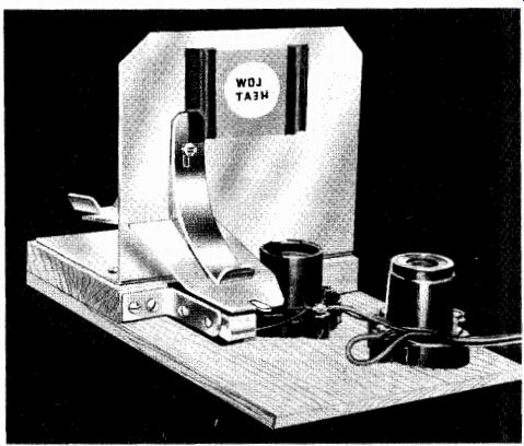
Fig. 76--Close-up of completed stand from opposite side. The socket in the
foreground is used to plug in the iron, the other near rocker-holds a 100-watt
bulb.
Workbench Tricks
There are a number of ways to make your workbench more convenient to use. If you use a soldering iron in preference to a soldering gun, you will find that a soldering stand which automatically controls the heat of your iron is a useful accessory. The stand, shown in Fig. 72, features a rocker arm rest which triggers a simple circuit to regulate the voltage supplied to the iron's heating element. For light soldering, there's enough heat in the tip at all times to do a good job. When high heat is required, the iron is ready for use about fifteen seconds after lifting it from the soldering stand.
A steel-wool cup on the stand provides a readily accessible place in which to brighten the faces of the iron. Insert the tip of the iron into the pad and rotate it once or twice. Another cup on the base of the stand contains rosin flux. The cover on this cup not only protects the flux when it is not being used, but it also serves as a high heat rest for the iron. This rest can be used when you want maximum heat from the iron during a heavy soldering job.
Construction of the stand is best seen in photos and captions. (Figs. 73-76). The parts list gives all of the required dimensions.
The simple wiring for the heat control is given in Fig. 77.
PARTS LIST
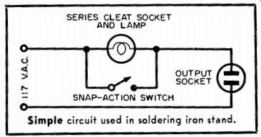
Fig. 77--Circuit for heat control unit.
A simple holder for your soldering iron can be made from a TV antenna mounting base (see Fig. 78). The base is about 4 inches high and 3 inches wide, with a clamp to fit the handle of the soldering iron.
For intermittent use the iron can be held with the base attached, and then the complete assembly can be set aside when the job is finished.
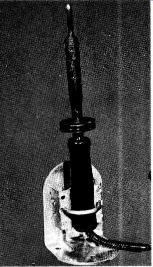
Fig. 78--A TV antenna mounting bracket used as a stand for soldering iron.
Clamp can be tightened to attach it to the iron.
Parts storage is always a problem for the experimenter, but there are a few tricks that can be used to help solve the problem. Muffin tins borrowed from the kitchen make an excellent place to keep screws, nuts, solder lugs, and other small parts. Different size parts can be placed in the separate compartments where they will be easy to pick out and will stay sorted.
Ice-cube trays make an excellent storage place for small parts.
These trays, made from either plastic or lightweight metal, make a suitable container for resistors, capacitors, washers, and miscellaneous hardware. The tray shown in Fig. 79 has twenty-eight small sections and will take up little space on the workbench. The individual compartments can be enlarged to fit bigger components by breaking off the dividing walls.
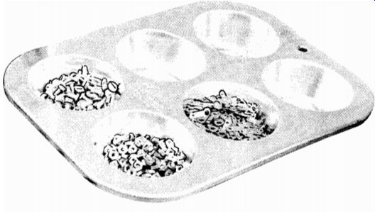
Fig. 79--A muffin tin and an ice cube tray are useful for parts storage.
Glass jars are ideal for more permanent storage of parts and hard ware. However, you then run in to the problem of how and where to store the jars. Two solutions to this problem are presented here. Both are satisfactory, and your choice will depend on the space you have available. In the technique shown in Fig. 80, a board is cut to fit into an area on your workbench, with enough clearance behind to fit the jars you are using. The holes are cut just large enough to let the jars slope slightly backwards when inserted. The jars are supported at the back with strips of 1/2-inch by 1-inch molding, available at any lumberyard for a few cents a foot. The contents of each jar can be printed directly on the cover for easy identification.
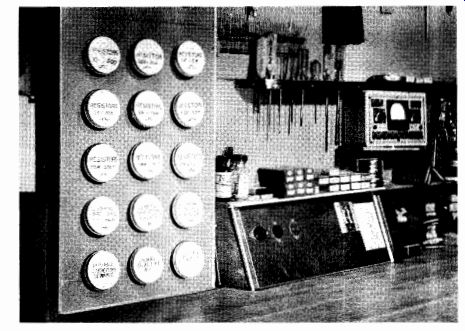
Fig. 80--Rack for storage jars can be made from plywood panel, Masonite, or
scrap wood.
Another way to use storage jars is shown in Fig. 81. The lid of the jar is installed on the underside of a shelf, using two small screws. The jars are then hung from the lids. The advantages of this system are that the contents of the jars are readily visible and that the jars take up no shelf space.
As you add to your collection of tools, you may find yourself short of rack space. Old typewriter ribbon spools can be used to add tool racks at minimum cost and effort. Nail the spools to the side of your bench or to a strip of wood as shown. Space the spools to hold the tools you have. The rack can be made to accommodate pliers, screwdrivers, nut drivers, files, and most other hand tools.
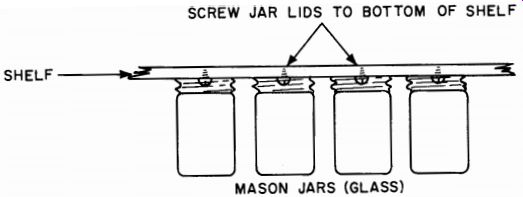
Fig. 81--Screwing jar top to underside of shelf makes a convenient jar storage
rack.
A final suggestion for making your bench an easy place to work is to mount your voltmeter in a tilting rack for easy use. It is often difficult to get a head-on look at your meter dial. It is either too high or too low, or it's not facing you squarely. Under such conditions it is often impossible to get accurate readings. The rack shown in Fig. 82 solves this problem. With this rack, it is a simple matter to adjust the tilt of the meter face for easy reading. This mount can be simply constructed from wood scraps in less than an hour.
Dimensions are not given because they will depend on the size of your particular meter. However, be sure that the mount you build provides adjustment for tilting and has a large, heavy base for stability.
There should be just enough room around the meter for easy removal of the instrument for use away from the shop.
In the unit shown in the photograph, a heavy oak base was used for weight and stability. The frame around the meter has a neat sliding fit. A narrow strip across the top back of the handle holds the meter in place and still permits easy removal.
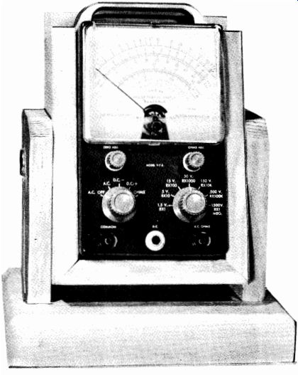
Fig. 82.