AMAZON multi-meters discounts AMAZON oscilloscope discounts
As you progress in your electronic experimenting, you will need equipment that will enable you to test, calibrate, and trouble-shoot your projects. The easiest way for the beginner to obtain test equipment is to buy it in kit form and assemble it himself. The instructions with kits are detailed and all parts are ready for mounting on a predrilled chassis. Often, you can buy a kit for less than the parts would cost for a home-built project.
Although home-built units have the advantage of giving layout and construction experience that you won't get from kit or factory-built units, commercial equipment has flexibility and accuracy not usually available in home-built equipment.
Which Instrument First?
The type of test equipment you need will depend on the area of electronics that interests you most. A voltmeter is basic to all types of electronic work; beyond that, your choice of instruments will be determined by your area of interest.
The usefulness of other test units will be determined on the basis of the type of equipment you are going to build. The audio fan will need an audio signal generator and the ham enthusiast will want an r.f. oscillator. The only major piece of equipment not included in this section is the oscilloscope. An oscilloscope project is difficult, and the parts required are expensive. If you want to build your own, investigate those designed and sold by the kit companies.
Make Your Own Multi-tester
The first piece of test equipment to be acquired by the electronic experimenter is, usually, a multi-tester, or VOM. Once in a while, though, this acquisition is delayed while the necessary capital ac cumulates. The multi-tester described here is not intended to replace any of the VOM's or VTVM's available in finished or kit form, but it will enable you to have the fun of electronic experimenting while you are waiting for the "real thing." Best of all, it's guaranteed not to deflate any but the most meager of pocketbooks.
The neon tester will measure a.c. voltages between 40 and 200 volts, d.c. voltages between 60 and 300 volts, and resistances between 10,000 and 250,000 ohms.
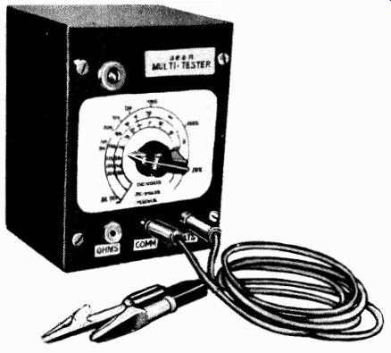
Fig. 110--Multi-tester with neon bulb which is used for economical construction.
A minimum amount of time is necessary to construct the tester.
As a matter of fact, to duplicate the unit described requires only the drilling of seven holes. The tester was housed in a 3-inch by 4-inch by 5-inch metal utility box. As there are no critical components or wiring in the unit, successful operation is practically guaranteed after construction and calibration.
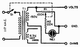
Fig. 111--Schematic diagram of multi-tester unit.
PARTS LIST
1-7" X 9" X 2" aluminum or steel chassis. (Bud CB-790, CB-1192, AC-406; ICA 29006, 4004, 1569; Par-Metal B-4511, C-4511; Premier CH-404) 3-Ft. #12 tinned bus bar; 4-Ground lugs 30-Inches 1" X 1" X 1/16" extruded aluminum angle. (Reynolds "Do-It-Yourself") 2-7-terminal tie-point strips (Jones #2007) 2-Sq. ft. .050 sheet aluminum or 20 ga. steel.
(Amount depends on number of brackets and adaptor plates)
1-Pkg. #6 X 3/8" sheet metal screws
Wire the power transformer T1 to the panel but mount it inside the box. (The transformer leads are not long enough to mount both the wire and the transformer inside the bottom of the box.) Mount the neon bulb (NE1) by forcing it into a rubber grommet on the panel of the instrument. Be sure to mount the grommet on the panel first, then gently slide the bulb into it. Also, don't forget to use insulated tip-jacks through the metal panel of the instrument. However, if you make your own box out of Masonite or plywood, this won't be necessary.
The filament winding on the power transformer is not used. Taping up these leads is a better practice than simply cutting them off, for you may eventually want to use the transformer for another purpose.
The voltage calibration of the neon tester is best accomplished by comparing it with another multi-meter. Meters of this type are available in such great profusion that you should have little difficulty in borrowing one temporarily. If a friend with a VOM is not immediately avail able, try the local radio/TV service shop. The calibration can be done "on the spot" in a few minutes if the procedure and necessary test setup are prepared beforehand.
ANY COMMON RECEIVER TYPE POWER TRANSFORMER SUPPLYING AT LEAST 300 VOLTS
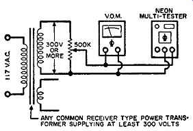
Fig. 112--Voltage calibrating setup for multimeter.
Before beginning the actual calibration, prepare a finished blank scale. It should consist of three concentric circular scales without calibration marks. For best results and greater durability, use India ink in preparing the scale and, later, in making the calibration marks and figures. The scale can be made on a white index card.
Put the blank scale in place on the front panel of the tester. Because you will want to remove it later for the finishing touches, fasten it in place with two small tabs of Scotch tape.
Voltage calibration can be effected with the setup shown in the diagram. The transformer, which can be any common receiver-type power transformer, supplies the voltage necessary to calibrate the upper end of the scale. With the 500K pot adjusted so that the "standard meter" reads 40 volts, adjust the neon tester control (R1) until the neon just ignites and begins to glow. The voltage at this point (as read on the "standard meter") should be marked on the blank scale in pencil. The pencil mark will be inked over later.
Adjust the 500K pot to 45 volts and continue to adjust the neon tester control until the neon just glows. Then mark this new point on the scale. Continue until the scale is completely calibrated with as many points as desired. This one procedure calibrates both the a.c. voltage scale and the d.c. voltage scale.
Ohms calibration is best accomplished by digging around in the junk box and finding as many different resistor values as possible be tween 10,000 and 250,000 ohms. If you are missing any essential values, they can be made from series or parallel combinations of available resistors.
To calibrate the ohms scale, place the known resistance between the common and ohms lead of the neon tester and adjust R1 until NE1 just begins to glow. Mark this point on the scale with the resistance value of the resistor. Continue the procedure until sufficient resistance points have been obtained.
Remove the pencil-calibrated scale from the neon tester. Now, simply multiply the a.c. scale by 1.41 and mark in the d.c. voltage calibration.
For example, the a.c. voltage calibration of 100 volts will correspond to the d.c. calibration point of 141 volts. The reason for this becomes apparent when we realize that an r.m.s. a.c. voltage of 100 volts, as read on any meter, has a peak voltage of 141 volts. Because the neon lamp in the tester responds to the peak voltage applied, a d.c. voltage (which of course has a peak voltage corresponding to its average value) will read 1.41 times the a.c. voltage.
Then go over the pencil-calibrated scale with India ink. The surface of the scale can be coated with polystyrene Q dope to give it a hard, glossy finish. If the lettering is carefully done, the results will look quite professional.
The neon tester is now ready for operation. When you use it, adjust R1 to the point where the neon lamp lights up.
Vacuum-tube Voltmeter
The vacuum-tube voltmeter (VTVM) as described here can be built at very low cost. It has an input impedance of 12.7 megohms on all ranges and three d.c. voltmeter ranges of 0-6, 60, and 600 volts full scale. There are also three ohmmeter ranges, which make measurements of 10 ohms to 10 megohms quite feasible.
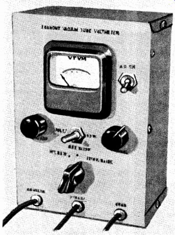
Fig. 113-Low-cost VTVM.
A 0-1 milliampere meter is used.
This can be purchased for approximately $3.50. (Any 0-1-milliampere meter can be used-the determining factor is mainly one of price.) The meter is of the moving-vane type and has an internal resistance of about 1,000 ohms. If a moving-coil type of meter is used, a 910-ohm, 1/2-watt resistor should be placed in series with the meter when it is employed in the VTVM.
The VTVM is housed in an aluminum case which measures 7 inches by 5 inches by 3 inches. Layout and construction details can be seen in the drawing and photograph.
A big item in the economy of construction is the use of 5 percent resistors for the voltage divider and ohmmeter multiplier. Some of the resistors in the voltage divider and ohmmeter multiplier are in parallel in order to achieve the exact calculated value. For example, one of the values called for was 900,000 ohms. Because this is not a standard value, two 1.8-megohm resistors, which are standard, were placed in parallel (see R5 and R6, R7 and R8).
PARTS LIST
B1--4.5-volt "C" battery (or 3 penlite cells in series)
C1, C2-50-ufd., 25-volt electrolytic capacitor
C3-.01-ufd.,600-volt ceramic capacitor
M1-0.1-ma. Shurite meter or equivalent (see text)
R1, R14--2.7 megohm, 1/2-watt, 10% resistor
R2, R3-1000-ohm potentiometer
R4-5000-ohm potentiometer
R5, R6-18-megohm, 1/2-watt, 5% resistor
R7, R8-1.8-megohm, 1/2-watt, 5% resistor
R9-100,000-ohm, 1/2-watt, 5% resistor
R10-100,000-ohm, 1/2-watt, 5% resistor
R11, R12-1800-ohm, 1/2-watt, 5% resistor
R13-100-ohm, 1/2-watt, 5% resistor
S1-S.p.s.t. toggle switch
S2-D.p.d.t. toggle switch
S3-3-pos., 2-pole rotary switch
T1-Power transformer, 125 volts of 15 ma., and 6.3 volts, at 0.6 amp.
(Stancor PS8415)
V1-12AU7 tube
The d.c. volts test lead should be a shielded cable. A 3-foot length of single-conductor microphone cable is ideal for this purpose. The common test lead and the ohms test lead are made of standard rubber-covered test lead wire. No jacks were used for the test leads as there is no need to disconnect them.
The most painstaking operation in constructing the VTVM is making the meter scale. First, disassemble the meter by bending up the four ears on the back of the meter. Next, carefully remove the scale.
Lay the scale on a piece of paper and fasten it temporarily in place with Scotch tape. Divide the scale into six equal parts (the meter scales are to be multiples of six instead of ten). Use the meter readings listed in Table 1.
--

TABLE 1
TABLE 2
Transfer the scale calibration to a new scale. (This can be drawn on a white index card.) Make an arc corresponding to the original meter-scale arc. Draw lines to the seven division points; this will divide the scale into six equal parts. Now subdivide each of the six dimensions into five equal subdivisions; these correspond to 0.2, 0.4, 0.6, and 0.8.
The next step is to draw in the ohmmeter scale. Do this by referring to Table 2. Draw another arc for the ohmmeter scale just above the voltmeter scale. From the data in Table 2, draw a line on the new scale through the center point and the voltage scale reading indicated.
The arc and calibration points and the lettering for both scales can be inked in with India ink and the pencil guide lines can be erased.
The scale can then be cut to size. Use paper rubber cement over the original meter scale to hold it in place.
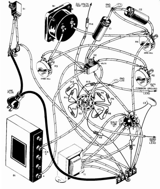
Fig. 114--Pictorial wiring diagram shows how various components are connected.
Note particularly the wiring around switch 53 and shielded lead attached to
R14.
After the unit has been constructed, the only calibration necessary is that for the d.c. voltage. A 4.5-volt battery can be used as a convenient source of known voltage. Temporarily remove the battery from the circuit. Set the meter to the 6-volt position. Set R4 so that the meter reads zero. Connect the voltage test probe to the positive end of the 4.5-volt battery, then connect the common lead to the negative end of the battery. Adjust R2 inside the VTVM so that the meter will read 4.5 volts.
This automatically calibrates all the voltmeter ranges. The battery can now be reinstalled in the VTVM.
The ohmmeter is calibrated in use by adjusting R3 on the front panel for full scale when the function selector switch is in the ohms position.
Check Your a.c. Calibration
After you have finished putting together the VTVM, a stable a.c. voltage source will serve to adjust the calibration of the a.c. scales. When you are going to make some critical a.c. measurements, you can recheck the accuracy of your VTVM or multi-meter with a voltage calibrator.
Calibration of the d.c. ranges of a meter is relatively simple because dry cells and batteries are universally available. Flashlight cells have an output voltage of 1.54 volts when new. "B" batteries are available in standard 45-, 67.5- and 90-volt sizes for calibration of the higher voltage ranges.
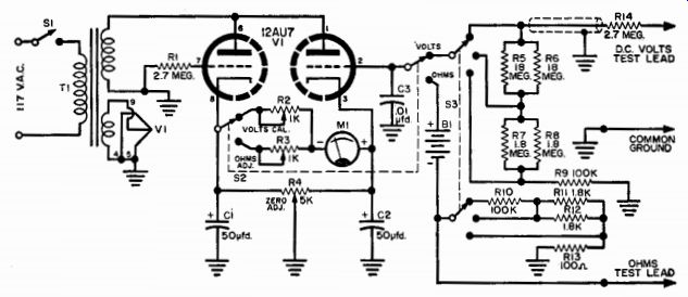
Fig. 115-Wiring diagram of test instrument. Note absence of rectifier which
is found unnecessary in this circuit.
Two 67.5-volt batteries, for example, can be connected in series to give over 135 volts in order to check the meter scale in the 150-volt section where many important measurements are made. (Actual voltage of each battery, when fresh, will be 69.3. The output voltage of a fresh battery is a physical constant and is dependent on the electro chemical makeup of the battery.) Calibrating the a.c. ranges of the meter is a problem. The power-line voltage, which is your source of a.c., varies from instant to instant and from hour to hour. Another a.c. meter of known accuracy which is needed to check the power line and a.c. scale is usually not readily available.
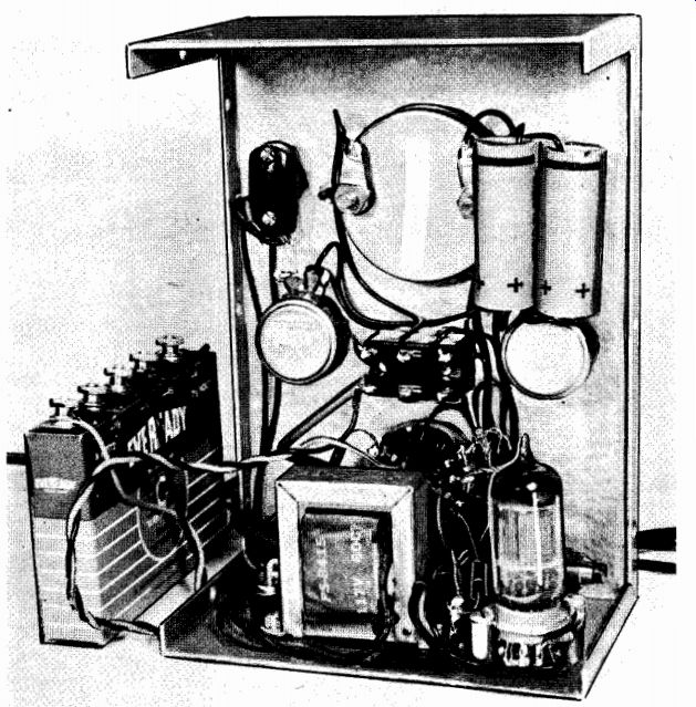
Fig. 116-Inside-the-case view of VTVM shows placement of parts used in original
model.
Here is a simple means of calibrating the a.c. ranges by means of the previously calibrated d.c. voltage ranges. All that is required is a simple half-wave rectifier system. Use a 130-volt selenium rectifier (SR1) of 30-milliamperes or higher current rating, a 22-ohm surge resistor (R1), and a 22,000- to 47,000-ohm load resistor (R2). A 0.2- or 0.5-microfarad capacitor plus some wire and solder completes the parts list.
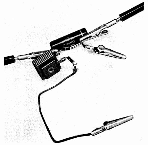
Fig. 117--Circuit of voltage calibrator is so simple that a chassis is not
necessary.
Measure the d.c. voltage across points C and D in Fig. 118. It almost equals the peak value of the a.c. voltage. Allow for about 1 percent drop through R1 and SR1. Now switch the meter to its a.c. voltage between A and B. Set the a.c. calibration control of the meter to read 0.7 (actually 0.707) of the previously measured d.c. voltage.
For example, if the d.c. voltage across C, D is measured as 160 volts (this would correspond to the peak a.c. voltage) the a.c. r.m.s. voltage is 112 volts (160 X 0.7). Because the line voltage may vary from one moment to the next, switch back to the d.c. scale immediately after setting the a.c. calibration control. Recheck the d.c. reading, then switch back again to the a.c. scale to recheck the line voltage, which may have shifted.

Fig. 118-Circuit layout of voltage calibrator.
Certain precautions should be observed, as this little gadget is operated directly from the a.c. line. Never touch the metal cabinet of your meter or uninsulated sections of the test probes and an external ground simultaneously. Make all connections and disconnections of your test clips or probes only when the calibration circuit is not plugged in.
Do not touch any water pipes, and avoid damp floors when working on any device which has its common or B- return connected directly to the a.c. line.
Economy Transistor Checker
The Economy Transistor Checker performs two sensitive tests which will quickly tell you if a transistor has been damaged due to overload or contamination of the germanium; if the transistor is shorted or open-circuited; or if it is just excessively leaky.
Construction of the transistor checker should take about one evening. It is housed in a 3-inch by 2-inch by 5 N-inch Minibox. The layout is not critical.
The transistor socket requires a 1/2-inch by 11/32-inch rectangular hole. Lay out the hole size carefully on the front panel with a scriber, then drill two 1/2-inch holes within the rectangle. The remaining aluminum can be readily removed in a few minutes with a small file.
Mount the 6-volt battery on the rear cover of the checker. Bend the strap of scrap aluminum so that it fits around the battery and clamp it firmly into place.
Wiring the unit should present no problem if the wiring shown in the diagram is carefully followed. If you have never worked with transistors, you should realize that particular care must be exercised regarding battery polarities and short circuits, etc. Usually, you get only one chance with transistors-unless you're fortunate and fast.
Solder the wire from the checker directly to the battery terminals.
The battery should last for its shelf life, since battery drain is small and intermittent.
To test a transistor in the checker, it is first necessary to know which basic type of transistor you have, i.e., whether it is a PNP or NPN type. You can determine this from the manufacturer's description or from the polarity of the battery connections to the transistor if it is in a piece of equipment. A PNP transistor always has the collector supplied from the negative pole of the battery and the emitter supplied from the positive pole. The NPN type is reversed completely, i.e., the collector is supplied from the positive pole and the emitter from the negative pole of the battery.
Once this fact is established, it is only necessary to set the switch on the checker front panel to the leakage position for the type of the transistor under test. Plug the transistor in the socket provided and observe the reading on the meter. The data in Table 3 gives representative readings for several transistor types.
TABLE 3. Typical leakage and gain readings obtained for several different types of transistors.
Transistor Type No.
Leakage Reading
Gain Reading
CK722 0.1 0.3 2N107 0.1 0.5 2N45 0.2 0.4 2N78 0.05 0.55 2N94 0.0 0.3 2N137 0.1 0.7
In general, the lower the leakage, the better the transistor. It can then be noted that the inexpensive low-frequency types usually exhibit higher leakage than the more expensive low-frequency types.
To check the common-emitter current gain, set the switch to the gain position. An upward swing indicates a current gain. If the leakage reading was very low, the meter reading, multiplied by 100, can be called the approximate "beta" (p) for the transistor. At any rate, the meter reading can be checked against Table 3.
If the transistor has an appreciable amount of leakage, the current gain (i3) can be obtained by observing the change in meter reading when switching from the leakage to gain positions. The difference between these two readings divided by the change in base input current which occurs when switching between leakage and gain positions will give the common-emitter current gain. For example, in the transistor checker the base input current is 10.7 microamperes. Thus, if the meter records a change of 03 milliampere in going from leakage to gain positions, the approximate current gain would be 0.0005 divided by 0.0000107, or 46.7.
Many manufacturers rate transistor gain as "alpha" (a), which is the common base current gain. This is a number always less than "1' for junction transistors and is generally of the order of 0.98.
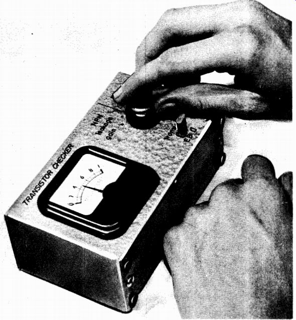
Fig. 119-Transistar checker.
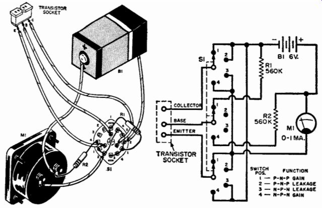
Fig. 120-Pictorial and schematic diagrams show haw parts are interconnected.
Power Supply for Transistor Experiments
The transistor power supply shown in Fig. 121 is a high-quality unit which has been designed especially for experimental test-bench operation. It is capable of handling a current tremendously greater than will ever be required in the average transistor setup, and the potentiometer specified will take many, many thousands of operations before it even feels inclined to wear out. Cheaper potentiometers begin to wear out relatively soon after being put into operation-and once wear begins in earnest, the wiper and the resistance element "go to pot" in a hurry.
A diffused junction germanium 1N91 rectifier has been used to provide a low voltage drop. The 1N91 is very small, considering its current-handling ability, and it costs little more than a selenium unit of the same rating. A pair of 25-microfarad electrolytic capacitors and a 8.5-henry choke take care of adequate filtering. A 1,000-ohm bleeder resistor connected across the input to the filter maintains a constant load on the supply. Everything runs cool except the potentiometer, which has a fairly high current running through it to overcome any tendency to ward erratic operation due to varying contact resistance.
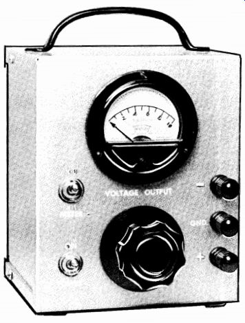
Fig. 121--Experimenter's transistor power supply.
Voltage output from the supply is continuously variable from zero to 30 volts d.c. A high-quality meter, connected across the output terminals, monitors the d.c. level. Two voltmeter ranges are provided:
The meter range itself-which is 0-10 volts; and an X3 range-obtained through the use of a 20,000-ohm, 1 percent precision series multiplier resistor which extends the scale to 30 volts. Each subdivision on the meter scale is equivalent to 0.2 volt on the low range and 0.6 volt on the high range. It is possible to set the output voltage to within one sub division, i.e., 0.2 volt, on the low range and better than one subdivision on the high range.
PARTS LIST
C1, C2-25-1.1 ufd., 25-volt electrolytic capacitor (C-D BBR-25-25 or equal) CH1-8.5-henry, 50-mo. filter choke (Stancor C-1279 or equal CR1-Diffused junction germanium rectifier (G.E. Type 1N91 or equal) M1-0-10 volt voltmeter, 1000 ohms per volt (Triplett 221-T or equal) R1-100-ohm, 25-watt potentiometer (Ohmite H-0151 or equal) R2-10-ohm, 1-watt composition resistor R3-1000-ohm, 10-watt wire-wound resistor R4-20,000-ohm, 1% precision resistor (IRC Type DCC or equal 52-S.p.s.t. toggle switch .11-25.2-volt, 1-ampere, filament transformer (Stoncor P6469 or equal) 1-4" x 5" x 6" 2-piece gray hammertone aluminum box 1-Screen door pull (for handle) 1-Rope cleat 1-Power cord 1-2-lug tie point 1-5-lug tie point 4-Sponge rubber discs (for feet) 1-Fluted knob, flange-type, 21/16" diameter 3-Binding posts
Misc.-hardware, solder lugs, extruded fiber washers, decals, rubber grommet, wire, solder, etc.

Fig. 122-Schematic diagram for transistor power supply.
The circuit diagram of the transistor supply is shown in Fig. 122.
The unit fits nicely into a 4-inch by 5-inch by 6-inch grey hammertone aluminum box. Both "+" and "-" terminals are insulated from the box by means of extruded fiber washers pressed into the holes from the inside. The Bakelite base of the terminal provides insulation on the panel side. The center, or gnd, terminal is connected directly to the box to permit the box to be grounded whenever necessary. Either the "+" or "-" terminal may be grounded to the box simply by connecting a short jumper wire between the appropriate terminal and the center terminal.
The meter multiplier resistor is located on the meter switch. All other resistors and capacitors are secured by their leads to a 5-lug tie strip which, in turn, is secured under the nut of the negative terminal on the meter. The diffused junction germanium rectifier connects be tween the uppermost terminal on this strip and the center lug on the potentiometer. A 2-inch to 2.5-inch length of No. 20 bare, tinned copper wire is soldered to the lower lead of the rectifier to extend its length. A long lead is desirable here because the potentiometer runs hot, and the greater length allows the heat conducted to the lead to be dissipated before it can reach the rectifier.
A series of 3/8-inch-diameter holes drilled in the back of the box permits adequate ventilation for the potentiometer. Direct ventilation can be obtained by drilling a 1-inch-diameter hole in the bottom of the box directly under the potentiometer. In this case, the series of holes at the bottom of the back cover of the box can be eliminated. Either method will work well, because the heat dissipated by the potentiometer is not severe. A 2-lug tie point, secured under one of the screws holding the filter choke, takes care of the power-cord connections.
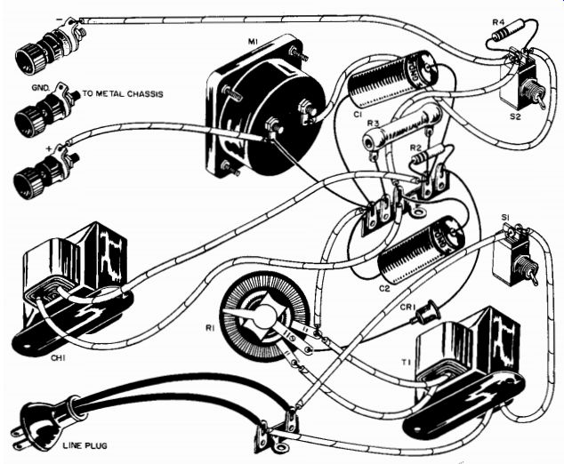
Fig. 123-Pictorial of power supply shows how parts are interconnected.
When using this supply, keep in mind that adequate series resistance should be employed in all necessary leads to prevent transistor burnout in the event of a runaway circuit. This is, of course, no different from the precautions which should be taken when batteries are used.
Buy all the batteries you like for your finished transistorized equipment, but build this supply for use on your experimental bench. Not only will it give the voltage you want when you want it, but it also will tell you what batteries will be needed for finished jobs as well. You can extend the life of the batteries in portable transistorized equipment by operating the equipment from this supply whenever you are at home and an a.c. outlet is nearby.
Audio Oscillator
There is no need to emphasize the audio-frequency generator especially to the audio experimenter. For, in this field, it is as basic as a voltmeter.
The audio-frequency generator covers the entire audio-frequency range from 22 hz to 12,000 hz; such coverage effects quite a saving in the cost of switches and other components usually found in most audio-frequency generators. The frequency control is an inexpensive potentiometer rather than an expensive multi-gang variable capacitor or multi-gang potentiometer. And, best of all, only one tube is used.
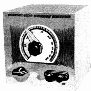
Fig. 124-Audio oscillator.
The oscillator is housed in an aluminum 6-inch by 6-inch by 6-inch box known as LMB Type 666. One-half of this box is an L-shaped piece which makes it convenient to use the box as the panel and base. No separate chassis is necessary. The unit is so simple that the parts can be easily mounted, wired, and serviced right on the bottom of the cabinet.
Mount the tube socket on metal standoffs or spacers to clear the socket pins from the metal cabinet. It is advisable to wire as many capacitors, resistors, etc., as you can to the socket before mounting.
Mount the two 3-watt bulbs (PL1 and PL2) by soldering the screw sides of the base to a terminal strip. Then solder the connecting wires directly to the lamp base. No lamp sockets are needed since the lamps are used at only a very small fraction of their rating and should last as long as any other component. Incidentally, don't expect to see any visible glow from these lamps when the oscillator is operating.
After the unit is constructed, the only adjustment necessary to put it into operation is calibrating the main frequency control. This could pose a small problem for some, because another piece of test equipment is required which you may or may not have.
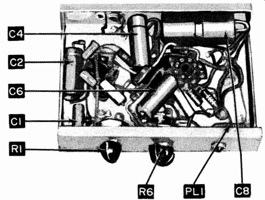
Fig. 125-View of audio generator. Note placement of major parts.
PARTS LIST
C1-10-ufd., 150-volt electrolytic capacitor
C2-0.47-ufd., 200-volt paper capacitor
C3-0.02-ufd., 200-volt paper capacitor
C4-0.01-ufd., 200-volt paper capacitor
C5-80-ufd., 150-volt electrolytic capacitor
C6a/C6b-40/80 ufd., 150-volt electrolytic capacitor
C7-25-ufd., 25-volt electrolytic capacitor
CH1-7-henry, 50-ma. choke (Stancor C1707)
PL1, PL2-3-watt, 115-volt lamp
R1-750-ohm, 1/2-watt fixed resistor
R2-270-ahm, 1/2-watt fixed resistor
R3, R4-10,000-ohm, 1/2-watt fixed resistor
R5-5-megohm potentiometer with reverse logarithmic toper
R6-470-ohm, 1/2-watt fixed resistor
R7-220,000-ohm, 1/2-watt fixed resistor R8-68,000-ohm, 1/2-watt fixed resistor R9-5000-ahm resistor R10-10,000-ohm potentiometer, linear taper
S1--S.p.s.t. switch on RIO SRI-65-ma. selenium rectifier TI-Power transformer, 125 volt at 15 ma., 6.3 volt at 0.6 amp. secondary (Stancor PS8415) V1-6U8 tube 1-6" x 6" x 6" aluminum box (LMS Type 666)
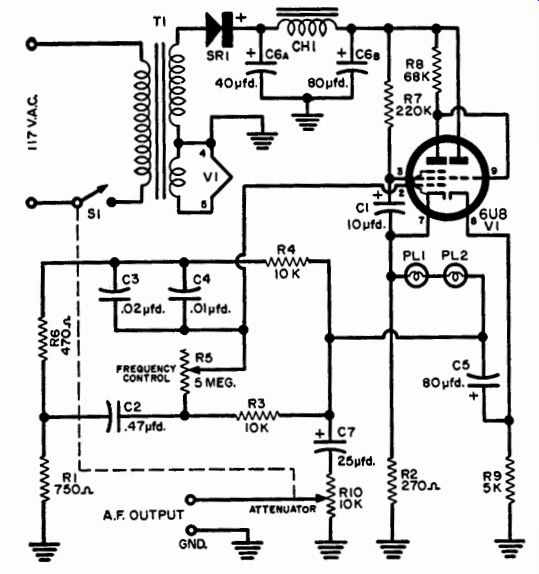
Fig. 126-Complete wiring details for audio oscillator.
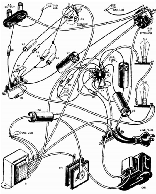
Fig. 127-Pictorial diagram of hook-up of audio-generator components.
(A) READ GENERATOR FREQUENCY DIRECTLY FROM A.F. METER SCOPE PATTERN WILL BE SLOWLY ROTATING CIRCLE AS OSCILLATORS ARE ADJUSTED TO SAME FREQUENCY. WHEN EXACT, SCOPE WILL EXHIBIT ANY OF THE FOLLOWING PATTERNS:
ECONOMY GENERATOR CALIBRATED A.F. GENERATOR (B) OSCILLOSCOPE
Fig. 128 (1)-Two possible methods of calibrating the audio generator.
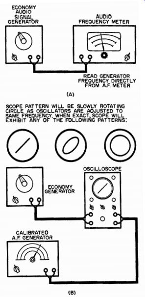
Fig 128 (2)-Three views of the signal generator chassis showing placement
of major components: (A) bottom view; (B) right side view; and (C) left side
view. Layout is critical.
Two possible methods of calibration are shown in Fig. 128 (1). It is assumed that you can borrow or obtain the use of the necessary equipment long enough to calibrate the audio signal generator. The method shown in (A) is the simplest. Feed the audio generator into an audio frequency meter which will read the signal output frequency directly.
The method shown in (B) is based on comparing the frequency out of the "Economy" generator with that of another calibrated audio generator known to be reasonably accurate. Feed one generator into the horizontal input of an oscilloscope. Feed the other generator into the vertical input of the oscilloscope. Set the calibrated generator on a frequency point to be calibrated. Adjust the uncalibrated generator until a circle or ellipse is obtained on the 'scope face. The two generators are then at the same frequency. This procedure should be repeated for all the points to be calibrated.
If you want to maintain the output absolutely constant over the entire frequency range, fixed resistor R1 can be replaced with a 1,000-ohm potentiometer. By adjustment of R1, the output voltage can be regulated. However, readjustment of R1 may produce an unfavorable effect on the output voltage. Therefore, it is recommended that R2 be changed, simultaneously, to a 1,000-ohm potentiometer. Thus, R1 and R2 can be adjusted for an output voltage of approximately 3 volts. The fixed-value resistors R1 and R2 constitute a happy compromise between economics and performance.
It is only necessary to remember that the generator will work into impedances over approximately 1,000 ohms with the attenuator control completely open, i.e., maximum output when you use the generator. It will work into lower impedances if the attenuator control is backed off slightly to introduce some resistance in series with the external load.
Of course, this will also reduce the output.
Another characteristic of the circuit, which is true of many RC oscillators, is that if the frequency control is changed suddenly, lamps PL1 and PL2 must adjust to new operating conditions. Because this oscillator has a wide range, it may take a second or two to overcome the thermal inertia of the lamps. This is quite normal in such an oscillator.
Operation, otherwise, is straightforward and should present no problem.
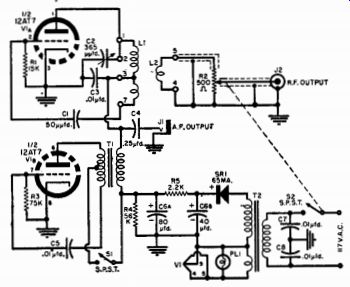
Fig. 129- Circuit of radio-frequency signal generator.
PARTS LIST
C1-50-µµfd. ceramic capacitor C2-365-1,0 ufd. variable capacitor C3, C5, C7, C8- 600-volt disc ceramic capacitor C4-0.25-p,fd., 400-volt paper capacitor C6-80-40-µfd., 150-volt electrolytic capacitor JI-Open-circuit jack J2-Coaxial jack PL1-Pilot light R1-15,000-ohm, I/2-watt resistor R2-500-ohm carbon potentiometer R3-75,000-ohm, 1/2-watt resistor R4-56,000-ohm, 1-watt resistor R5-2200-ohm, 2-watt resistor
S1--S.p.s.t. switch
S2-S.p.s.t. switch on R2
SR1-65-ma. selenium rectifier
T1-Modulation transformer, 4000-ohm secondary, 10,000-ohm center-tapped primary (Stancor A3812) T2-Power transformer, 125 volt @ 15 ma., 6.3 volt @ 0.6 amp. (Stancor PS8415) V1-Type 12AT7 tube
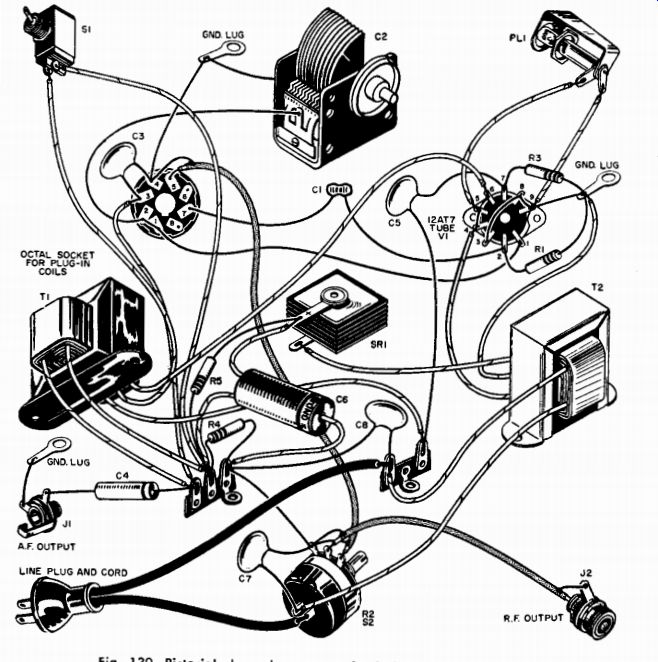
Fig. 130-Pictorial shows how parts of r-f signal generator are interconnected.
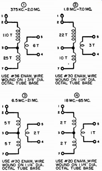
Fig. 131-Four coils required for basic frequency ranges. Use data given here
to wind coils. USE 036 ENAM. WIRE WOUND ON 1 3/8' DIA.
OCTAL TUBE BASE USE #30 ENAM, WIRE WOUND ON 1 ¼” DIA.
OCTAL TUBE BASE
USE #30 ENAM. WIRE WOUND ON 1 1/4" DIA.
OCTAL TUBE BASE USE #20 ENAM. WIRE WOUND ON 1 ¼” DIA.
OCTAL TUBE BASE
R.F. Signal Generator
This radio-frequency signal generator is fairly straightforward in electrical design. Although it uses only one tube, it offers a frequency range that can be spread or tailored to one's individual requirements.
This is achieved by the use of plug-in coils. It also results in a general cost reduction . . . particularly because the coil forms are free!
Four plug-in coils cover the range of 375 khz to 65 mhz. The generator incorporates an internal 400-cycle audio modulation. The audio tone is made available through the front panel to check audio systems, amplifiers, etc.
Mechanical considerations involved in building a signal generator are as important as the electrical design. Ever try to lift a high-quality laboratory unit? It often takes two men to transport it across a room.
Mechanically rugged and rigid construction is a primary aim in these generators.
The "Economy" generator can be lifted by a very small boy, but it has this same philosophy of good mechanical design in its layout.
A steel chassis and box are used purely for mechanical rigidity. The rear edge of the chassis has a metal post stand-off, and the plug-in coil bracket has a special metal post to hold it to the cabinet. These pre cautions make a fairly rugged unit in which the output is reasonably immune to pounding and vibration.
The unit is housed in a black crackle 6-inch by 6-inch by 6-inch steel utility box with a 4 1/8-inch by 5 1/2-inch steel shelf. The 12AT7 is mounted vertically under the chassis, and the coil socket is mounted on a right-angle bracket formed from a 1 1/8-inch by 2 1/2-inch piece of steel.
If short leads are maintained in the coil (L1) and variable capacitor (C2) circuitry, there will be nothing critical in the wiring.
The coil forms can be salvaged from defective octal tubes. Just make sure that the coil is wound on the diameter base specified. Break a tube in a paper bag with a sharp hammer blow. Clean out the base with a pair of cutters. Pick or scrape out the cement with a screwdriver.
Remove wires from the pins by heating the pins with a soldering iron.
After the solder has melted, give the base a sharp rap, and the hole in the pin will be clear of both wire and solder.
The post providing support between the rear chassis edge and cabinet and the post between the coil socket and cabinet are made up of standard 1-inch threaded metal spacers. They are fastened together by cutting the head off a screw and using the threaded portion to hold the two posts together.
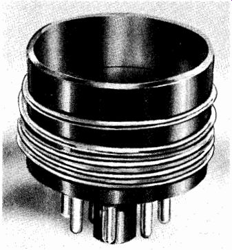
Fig. 132-Coil wound on salvaged octal tube base.
Calibration poses a more interesting challenge than building the generator, but an accurate and reliable calibration can be worked out with a good communications receiver.
An "all-wave" receiver can be used if it has a short-wave coverage up to approximately 22 mhz.
The calibration method described here uses broadcast-band stations of known frequencies.
These are made to beat against the genera tor fundamental and harmonics up through the highest frequency received by the receiver. The lowest frequency of the generator is around 375 khz.
Assume that there is a broadcasting station at 800 khz in your locality and that the receiver is tuned in to this station. Place the receiver antenna close to the generator output lead. If the low-frequency coil is plugged in the unit and the generator is set to the lowest frequency (i.e., the variable plates of C2 are all in), as the generator dial is slowly rotated toward the higher frequencies a beat note or whistle will be heard.
As the dial is rotated, the beat note will first be noticed as a high pitched whistle which decreases in frequency as the dial is rotated farther. This continues until zero frequency difference is reached. This is known as "zero beat." As the dial is 'rotated still farther, the frequency will again increase until it is inaudible. However, when the frequency was "zero beat" with the broadcast station at 800 khz, the genera tor was exactly set to 400 khz. Thus, the first calibration point has been obtained.
The generator frequency is increased until a carrier is heard. This indicates that the generator is set at 800 khz. That point is then calibrated on the generator. With the generator set at 400 khz, previously calibrated, the third and fourth harmonics of the generator can be picked up on the receiver at 1,200 and 1,600 khz. They will be considerably weaker.
After these frequency points have been calibrated on the receiver, more calibrated points on the generator can be determined as follows:
Set the receiver to the newly calibrated frequency of 1,200 khz on the dial. Continue to increase the generator frequency until a strong carrier (no whistle) is heard. This frequency will be 1,200 khz, calibrated on the generator dial.
Then set the receiver to 1,600 khz. You have determined four frequencies with good accuracy.
With the generator at 1,600 khz, scan the receiver frequencies starting at 1,600 khz for generator harmonic points. The first should be heard at 3.2 mhz, then 4.8 mhz, and a weaker one at 6.4 mhz.
Now set the receiver at the 6.4-megacycle spot and double check the lower generator frequencies. For example, as the generator frequency is increased, the next signal heard in the receiver will be that made when the generator is set at 3.2 mhz. This point is calibrated on the generator dial, and the generator frequency is increased until the carrier is heard at 6.4 mhz. Such a "boot strap" process can be repeated to the highest receiver frequency.
The generator frequencies beyond the highest frequency received by the short-wave receiver can be calibrated by using an FM tuner. Be cause generator harmonics will lie in the FM and TV bands, the procedure described above can also be used to extend the calibration of the generator.
Power Transistor Signal Tracer
With the possible exception of a volt-ohm-milliammeter, signal tracers are perhaps the most useful test instruments in the home work shop. However, a-c.-operated signal tracers have always been handicapped by their sensitivity to 60-cycle pickup. Battery-powered models, using vacuum tubes, have the disadvantages of high-battery drain, tube fragility, and low audio output.
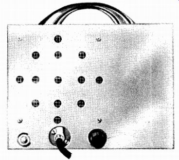
Fig. 133-Transistor signal tracer.
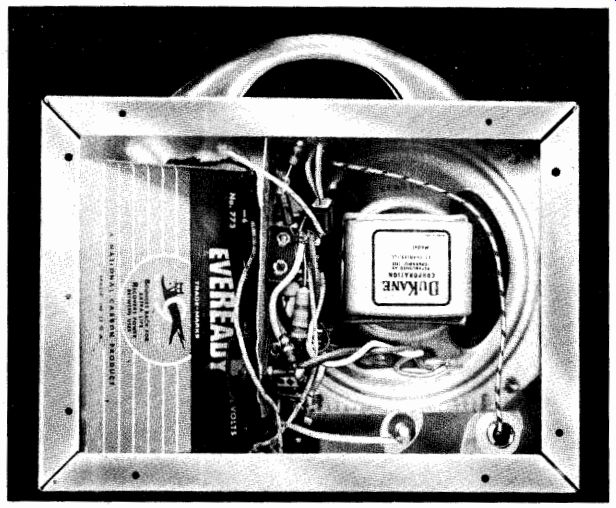
Fig. 134-Internal construction of power transistor tracer.

Fig. 135-Circuit of signal tracer uses three CK722's and one 2N255.
The "deluxe" model tracer shown in Fig. 133 incorporates four transistors and a self-contained 6-volt battery and has almost 1 watt of audio available at the output of the CBS 2N255 power transistor.
Construction is simplified by using a standard aluminum chassis as a cabinet. Cut a small, individual subchassis for parts mounting from a scrap piece of aluminum and bolt it directly on the speaker. Insulate the power transistor from the chassis and then plug it into a 9-prong miniature socket. Solder all other transistors and parts directly into place as the circuit is wired.
Place spaghetti on the collector and base leads of each transistor to prevent shorts to other components or to the chassis. Parts placement is not particularly critical, but try to keep the input components away from the output circuit.
Note that this model tracer has two separate input jacks labeled, respectively, "phono" and "probe." The probe jack (j1) is the input for the r.f. detector lead. This probe contains a crystal diode which demodulates the r.f. signal and allows the transistor audio amplifier to build up the signal to audible level.
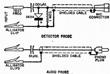
Fig. 136--These special probes should have all elements well shielded. The
detector probe components can be built into a small tube shield. All capacitors
should be 600-volt miniatures.
Thin lapel microphone cable can be used for utmost flexibility.
When testing in audio stages where less gain is required, use the phono jack input. This jack (j2) is fed by a shielded cable terminated on one end by a standard type phono plug and on the other by an isolating capacitor. For audio applications, such as crystal phono cart ridge testing or hi-fi amplifier servicing, this input is best.
Using the tracer for trouble shooting is simplicity itself. Turn the radio receiver on and tune it to a strong local station. Connect the signal tracer's ground lead to the receiver's chassis or "ground." Then turn the signal tracer on, adjusting gain control R4 for full volume.
Starting at the receiver's antenna, touch the probe to the "input" and "output" of each stage to check individual stage operation. If the pro gram is heard at one stage but not at another, check the circuit be tween them. Defective radios, hi-fi amplifiers, p.a. systems, TV receivers, and intercom circuits should present no problems for this little, transistorized signal tracer.