By J. A. "Sam" Wilson, CET
Inductance-type passive transducers are analyzed in this concluding coverage of transducers.
Resistive and capacitive types of transducers have been examined in preceding articles. In this part, the subject is transducers which change inductance according to the conditions being monitored.
Properties of Inductance
Here are two definitions of inductance: Inductance of a coil causes it to oppose any change of current through it. It is the characteristic that forces an inductor to oppose or impede the flow of alternating current.
Inductance of a coil enables it to store energy in the form of a magnetic field.
An inductor or coil operates by the magnetic field that surrounds the conductor of a current, so any change of field strength affects the operation of the inductor.
Inductive reactance
The opposition of a coil to the flow of alternating current is called inductive reactance (XL), and it is expressed in ohms.
Mathematically, XL = 2 pi FL. Therefore, the inductive reactance increases from an increase of frequency (F) and/or the increase of inductance (L). With inductive transducers, the varying reactance of the inductor determines the amount of circuit current, according to the condition of the material being sensed. In other words, a change of the condition that's being monitored produces a corresponding change of the reactance, and it in turn modifies the amount of current in the control circuit.
Effect of Cores
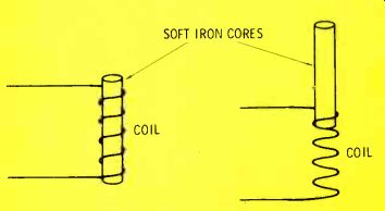
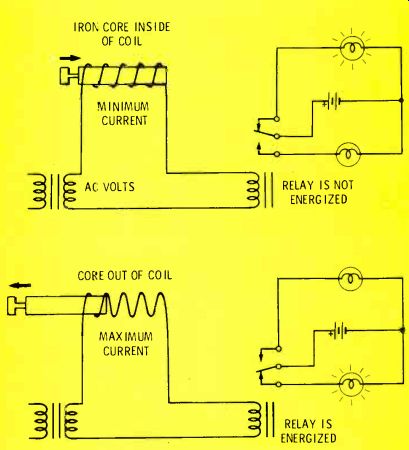
An iron core inserted into a coil (see Figure 1) produces an increase of inductance and inductive reactance. In practice, the core must be laminated or made of powdered iron to minimize the core losses at high frequencies, but this does not alter the basic principle. (In Figure 1, the term "soft iron" refers to iron that cannot permanently hold magnetism.) Position indicator One practical application of the core principle is shown in Figure 2.
When the core is completely inside the coil, the inductance and reactance "are maximum. Therefore, the current is low, and is not strong enough to energize the relay. The contact points are in the open position to illuminate the correct position light.
When the material being monitored is too far to the left, the core is withdrawn from the coil, reducing the inductance and the reactance, which allows increased current. The stronger current energizes the relay, pulling down the contact and illuminating the wrong position light.
Of course, the change of inductance and reactance is gradual, when the core is moved gradually, but the relay has a snap action so it either is on or off. For other applications, the gradual change of inductance can provide an analog meter readout of the position or dimension of a work item.

Figure 1--The inductance of a coil is increased by the addition of an
iron core.
For high -frequency operation, the core should be made of powdered-iron particles held in place by insulating material.

Figure 2--Position of an object can be sensed by connecting it to the
core of a coil. (A) When the core is inside the coil, the coil inductance
and inductive reactance are high, giving low current which does not trip
the relay. (B) Withdrawing the core reduces the inductance, allowing
increased current that trips the relay.

Figure 3--A "tuning wand" (A) has one tip of copper and one
of iron. (B) Current is less than normal, because the LC circuit resonates
below the input frequency. (C) Inserting the copper tip of the wand reduces
the coil inductance, raising the resonant point to 100 KHz, and producing
maximum current. (D) When the wand iron tip is inserted in the coil,
the inductance is increased, lowering the resonant point to 96 KHz, which
reduces the current below the original amount.
Using a tuning wand
A copper core in a coil decreases the inductance, while a powdered iron core increases the inductance. These two actions can be combined in a helpful tool for determining whether an inductance is too small or too large for the best operation of a circuit. The tool is a "tuning wand," illustrated in Figure 3A. As we go through the explanation, remember that the current through a series -tuned circuit is maximum at the resonant frequency.
In Figure 3B, the resonance of the tuned circuit is below the input frequency; therefore, the alternating current is not maximum, but has an intermediate value. When the copper end of a tuning wand is inserted into the coil (Figure 3C) the coil inductance is decreased, raising the resonant point to 100 kHz, and providing maximum current.
Inserting the powdered-iron tip of the wand into the coil (Figure 3D) increases the inductance and lowers the resonance to 96 kHz.
This additional mistuning results in a small current.
With parallel-tuned circuits, the signal voltage is monitored as the two tips are inserted in turn. If both tips reduce the signal equally, the tuned circuit is adjusted to the correct frequency. If the copper tip increases the signal level, the frequency of the tuned circuit is too low. Conversely, a signal increase with the iron tip proves the frequency is too high. Of course, the amount of correction by the wand is limited, so no change probably indicates an error that's too large to be helped.
The Effects Of Turns
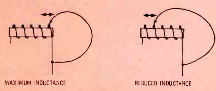
Additional turns of wire on a coil increase the inductance. In practical devices, it is difficult to vary the number of turns except by means of a shorting bar (Figure 4). Shorting across three turns of the coil is the same as removing three turns (except for a loading effect when the various turns have tight coupling; a lower load reduces the Also, the dimensions and shape of the coil winding affects the inductance. All of the coils of Figure 5 have the same number of turns, but each has a different inductance. The coil of Figure 5A is used as a standard. When the diameter of the coil form is increased (Figure 5B), but the number of turns and the spacing remains the same, the inductance is increased.

Figure 4 A shorting bar or shorting jumper gives the effect of removing
turns from a coil, thus decreasing the inductance.
But, if the diameter and number of turns are the same, a wider spacing of the turns on a longer coil form decreases the inductance.
(Equations for inductance can be simplified by relating the inductance to the core area, rather than to the core diameter. Therefore, it is not necessary to specify the cross-sectional shape of the core.)
Magnetostriction Effect
Magnetostriction refers to the dimension change of magnetic material when it is affected by a magnetic field. The Joule Effect is the name given to the change in length of a magnetic material when the magnetic flux through it is varied. Also, there is a reverse effect (called the Villari Effect), where a change of dimension of a magnetized material in turn changes the amount of magnetization.
Magnetostriction transducer Figure 6 shows one practical application of the magneto-restrictive effect: a transducer that converts an AC signal into high-energy, high -frequency sound waves. These supersonic sound waves clean dirty components that are immersed in a fluid. They literally shake the dirt loose and into suspension.
Other kinds of supersonic equipment are useful for testing and inspecting specific materials.
Variable-Reluctance Transducers
In diagrams, magnetic field strength usually is represented by flux lines. Stronger fields require more flux lines through a given cross-sectional area.
It is easier to establish flux lines in some materials-such as iron or steel-than it is in many other materials (such as air). Reluctance is the name given to the opposition that a material offers to the forming of flux lines.
The elements of magnetic circuits versus electric circuits sometimes are compared as shown in Table 1.
Incidentally, the term "electromotive force" would fit better in the table as a "cause." But the term no longer is in favor. In the new concept, a volt is a unit of work, and not a force. As used in science, work is equal to force multiplied by distance. A volt, then, is the amount of work done by moving a unit charge around a defined circuit. Also, to be technically accurate, we must say that magnetomotive force is measured in units of work.
From Table 1. you can conclude correctly that varying the reluctance of a magnetic circuit also varies the flux.

Figure 5 Changing the diameter of the coil winding and changing the
spacing between the turns produces a different inductance of a coil.

Figure 6 The magnetostrictive effect causes the length of a magnet to
vary in step with the AC signal from an amplifier.

Figure 7 This variable-reluctance circuit senses vibration by the movement
of a vane in the magnetic path. Position of the vane giving a large gap
(A) allows only a small flux to travel around the core.
When the vane bridges the gap (B), the flux is increased. Rapid movements of the probe and vane cause fast changes of reluctance and flux, producing an AC signal at the output winding.
Faraday's Law
Before studying variable-reluctance transducers, we should review the concept of Faraday's Law. It states that relative motion between a conductor and a magnetic field produces a voltage.
Transformers operate under this principle. Changes of primary current produce changes of flux around the secondary winding, which induces a voltage in the winding.
The variable -reluctance transducer of Figure 7 is designed to sense vibration. A DC current in one winding establishes a flux in the soft -iron circuit. When the sensor vane is at an angle to the gap (Figure 7A), the flux is at minimum because of the large air space.
Figure 7B shows the vane in line with the gap, allowing maximum flux through the low -resistance path across the small gap. Movements of the vane cause a varying flux, which produces an AC voltage at the output terminals.
Although this is an active transducer--because it emits an output voltage-it is presented because of the variable-reluctance operation.
Also, the principle, with minor modifications, applies to saturable reactors, which are passive components.
Magnetometer
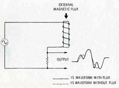
Magnetic fields can be sensed by the magnetometer of Figure 8. Complex versions are used to measure the strengths of magnetic fields accurately.
Here's how it operates: When there is no external magnetic field, the core of the coil saturates equally on the positive peak and on the negative peak of the signal source. An external magnetic field adds to the coil flux during one half-cycle and subtracts from it on the following half-cycle, producing a change of waveform. Changes of waveform have been exaggerated to demonstrate the point.

TABLE 1 Comparison Of Electric And Magnetic Circuits

Figure 8 External magnetic fields can be detected by phase and linearity
changes of the output signal. The external flux aids one peak of the
input AC, but it subtracts from the opposite peak.
Comments
When we elaborate about actual devices used in industrial sensors, one of the important types to be discussed will be the instruments that determine shaft rotation. For example, a magnet can be fastened on a rotating shaft. Each time it passes a coil of wire, a voltage pulse is produced. The repetition rate can be counted directly or it can be read-out on an analog meter.
Another variation has the coil wound over a magnet, and the pulse from the coil occurs each time an" iron or steel vane passes the coil.
(adapted from: Electronic Servicing magazine, Nov. 1977)
Also see: The Basics of Industrial Electronics, Part 6 (Dec. 1977)
The Basics of Industrial Electronics, Part 1 (Jun. 1977)