By Carl Babcoke, CET
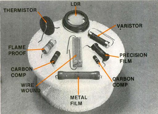
---- Several basic types of resistors are identified by arrows and
captions.
Resistors are available now in many different types and ratings.
They vary considerably in performance and stability. This information is compiled to help technicians select replacement resistors that will equal or exceed the original performances.
In previous decades when electronic products were less complicated, the choice of a small resistor for replacement was very simple.
First, the value in ohms was obtained from a schematic. Next, any new resistor of equal wattage (or larger, if it could be squeezed into the space) was installed. There were no other considerations.
When applied to late-model color TVs, unfortunately, this simple method might produce inferior pictures, or it could cause a delayed failure which extensively damages several other components. Yes, modern equipment demands that more attention be given to the selection of a proper replacement resistor from the many excellent types now available.
Although the rules for obtaining an appropriate type of resistor are few and not difficult, they are easier to remember after the reasons behind the rules are explained.
Therefore, some background information will be supplied first.
What is a resistor? The word "resistor" implies a component that resists something.
In this case it resists the flow of current. And in a secondary sense, it resists the effect of voltage.
With the few resistor types of 30 years ago, it would have been sufficient to define a resistor as a component having a voltage/current relationship that is both constant and linear. Although that definition excluded capacitors, diodes and inductors, it soon became obsolete with the introduction of unique resistors that changed resistance according to the amount of voltage, the exact temperature or the intensity of light falling on the resistor element. These interesting types of resistors will be explained later, and a better definition of resistors is proposed at the end.
Carbon-composition resistors
Carbon is the material used in the majority of resistors. Figure 1 shows construction details of the hot-molded carbon-composition type of resistor. Carbon is mixed with non-conductive binders and fillers to form the resistive center, which is combined with the 'end wires and the external insulation during one trip through an auto mated machine.
Hot-molded carbon resistors are available typically in wattages from 1/8 W to 2W. Smaller numbers of 3-W and 4-W sizes are manufactured also.
Variations of the carbon-versus-filler ratio and the physical size of the resistive element produce values between 10-o and 22M-o. These values can be held to a manufacturing tolerance of about ±10%. Then ±5% and f2% tolerance values are obtained by testing a whole run and removing those resistors that are within the tighter tolerances.
It's not practical to manufacture or select carbon resistors of better tolerances because the normal resistance variations from aging and heat cycles often exceed those limits. If tighter tolerances are needed, a more stable type of resistor should be selected.
Temperature coefficients of these carbon resistors are between +1000 parts-per-million (PPM) per degree Centigrade and-1000 PPM. How ever, the resistors have a small negative coefficient.
That is, the resistance decreases slightly from an increase of temperature.

---------- Two resistors were broken to illustrate the construction.
At the left in both pictures is the RCA flameproof type. The other is
a good-quality car bon-composition type. After they were broken, the
flame proof resistor was found to have a core of glass or some ceramic
that was smooth and reflective. The half held by thumb and finger has
had the insulation scraped to show the metal cap and the spirals of resistive
material. At the right, a center of carbon-and-filler and the insulation
(which is thick to provide strength) are the only visible parts of the
carbon-comp type.
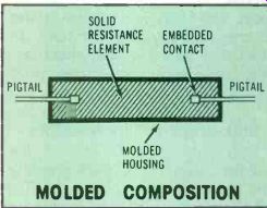
Figure 1---Hot-molded carbon-composition resistors are manufactured in
automated machines. Resistance values are indicated by the colors of
stripes around the body. Hot-molded carbon resistors are being superseded
slowly in new equipment by carbon-film types.
------------
Resistor Quiz
1. True/False Two 1-watt resistors always can dissipate 2 watts.
2. True/False Wire-wound resistors produce the least amount of noise.
3. True/False Varistors follow Ohm's Law.
4. True/False Film resistors have the least reactance of all types.
5. True/False Many carbon resistors change resistance after repeated hot and cold cycles.
6. True/False Don't replace any resistor with one of higher wattage.
7. True/False Hot-molded resistors have minimum skin effect.
8. True/False Carbon is the least stable of all resistive materials commonly used in resistors.
9. True/False All metal-film resistors are non-inductive.
10. True/False Resistor self-heating because of the power dissipated sometimes is an advantage.
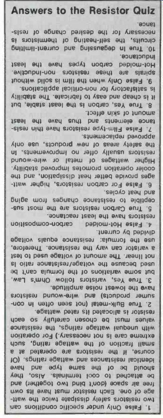
Answers to the Resistor Quiz
--------------
Carbon-film resistors
A thin film of carbon is deposited from a carbon-bearing high-temperature gas onto a cylindrical rod of ceramic or glass substrate. That's why this type of resistor sometimes is called a deposited-film type.
Finally, metal end caps with lead wires are crimped firmly over the ends, and insulating material is applied by molding or by dipping (see Figure 2).
For lower resistance values, the film is continuous from end to end.
Higher values require the carbon film to be placed (or cut) in spirals around the core. Extremely high values have one long continuous spiral which gives a long narrow path of carbon.
Carbon-film resistors usually are manufactured in values between 1 ohm and 200M-ohm . This type is gaining in popularity, and the number used per year probably will continue to increase unless the metal-film types overpower it by better stability.
Metal-film resistors Construction of metal-film resistors is similar to that of the carbon-film types previously de scribed. Thin-film types have a one-millionth-inch coating of chromium, nickel or aluminum.
Metal-oxide, bulk-property metal or glazed-metal are used for the thicker coatings.
When the coating is continuous, the basic resistance is only a few thousand ohms. Spiral grooves are cut in the metal film to increase the resistance value of each resistor, which can be trimmed this way to good tolerance. Flat designs can be laser-trimmed for very-high accuracy.
Metal-film resistors fall into two categories. One group includes high-accuracy, high-stability precision resistors that nearly equal the excellent performance of the best precision wire-wound types. The other group is made up of lesser-ac curacy resistors for uses where higher wattages and minimum drift of resistances are important. These latter types often are included in new equipment as an alternate to larger wire-wound resistors, or where the stability of carbon-com position is not satisfactory.
These metal-film resistors are manufactured by depositing Ni-chrome or other metal alloy on a glass or ceramic rod while the components are in a vacuum. The end caps with leads and the insulation are added later.
Cermet-film resistors--A mixture of precious metal and ceramic binders is screened onto a ceramic rod or tubing before it is "fired" at a high temperature to produce glazed metal and cermet film resistors. Cermet is a combination of ceramic and metal.
Generally, cermet resistors are smaller than the other types, they can be made in larger resistances up to 500 M-o, some types can-operate up to 8000 V/in of the body, and they are stable under adverse environmental extremes. In short, they have excellent characteristics that justify the higher price for many applications.
Bulk-property film resistors
Only pure metal is used as the resistive element in bulk-property film resistors.
They are limited to the middle of the resistance range (about 30-o to 100K-o ) and a maximum of 0.75 W, but they have excellent advantages such as these: the best high-frequency response of any type of resistor; availability in precision tolerances; a stable temperature coefficient; and very small noise contribution.
Except for a few limitations and the price, bulk-property resistors approach the ideal.
Flame-proof resistors---Flame-proof resistors are not basically different from others. Although little specific information could be obtained about the internal construction, many of them appear to be metal-film types. In any event, the flame-proofing consists of a ceramic or glass rod at the center in addition to an overall ceramic coating which will not burn or out-gas when the resistor is overloaded.
Flame-proof resistors can be used to replace many other types, but they especially are recommended for the safety areas marked on schematics.
Resistor stability It seems logical that a resistor should not change resistance at all after it is manufactured. That is not the case; all resistors change in value, but some types change more than others do.
Temperature---One major cause of resistance variation is temperature.
Ambient temperature surrounding each resistor and the internal rise of temperature from the power dissipated inside the resistor both contribute to resistance variations.
Changes from cycling---A resistor often undergoes a "retrace" change of resistance when operated alternately between room temperature and rated wattage. In other words, cold resistance following hot operation is different from the original cold resistance. Some resistors show a permanent significant change after only a few heat cycles.
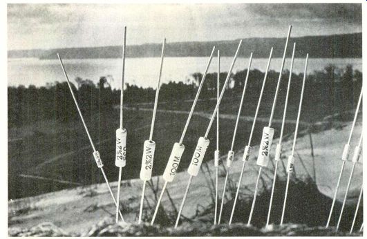
------------- These flameproof resistors are part of the replacement
line. (Courtesy of GTE- Sylvania) Sylvania ECG semiconductor
This resistance change from heat cycles was reported in the June 1970 issue of Electronic Servicing.
Of all the wire-wound, metal-film and carbon-composition resistors that were tested, only the carbon ones suffered any permanent change. One 0.5-W resistor was about 12% higher after only three cycles. A 1-W carbon had a permanent 17% increase after three heat cycles. The worst example was a 0.5-W, 3.3-M-ohm carbon type that increased a big 47%. None of these resistors showed any external change or signs of overload.
A similar test made this April confirmed the trend, although the resistors showed only moderate permanent increases after four or five heat cycles at rated wattage.
Probably these better results are explained by modern improved manufacturing techniques.
Overload tests---Both series of tests included operation of resistors in steps of increasing wattages above the ratings. The tests were stopped each time when the resistor showed visible signs of overload. When an overload of 10 times rating was applied to one half-watt resistor, the resistance decreased to about a third of the original value and the color-bands were scorched.
Other similar carbon resistors (not the ones heat cycled) showed a slight decrease of resistance when the ambient temperature was raised. They also measured slightly high when sprayed with canned coolant. According to these imprecise tests, they evidently had a small negative temperature coefficient.
Conclusions---Moderate permanent increases of resistance were measured following tests that operated these carbon-composition resistors between zero watts and rated watts for several cycles. However, any massive overload decreased the resistance by a huge amount.
This characteristic of carbon to reduce its resistance from strong overloads (rather than burn open) is one reason why carbon-type resistors are seldom recommended in the safety areas of electronic circuits. Such near-shorts could allow extra damage to other components.
Safety resistors should either open or maintain the original resistance.
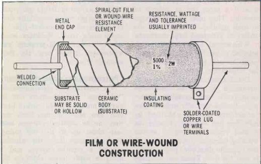
Figure 2---Carbon-film and metal-film resistors usually have each resistance
element arranged in a few spirals to lengthen the path and thus increase
the resistance. Lead wires serve as connections. Colored bands around
the body indicate the resistance and tolerance. By contrast, wire-wound
resistors have a tight spiral of many turns of resistance wire. They
might have lugs or lead wires (or a combination of both), and the specs
are printed on the bodies which usually are round but covered with vitreous
enamel or a square ceramic covering. FILM OR WIRE-WOUND CONSTRUCTION
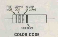
Figure 3---This is the standard color code for all small resistors.
COLOR CODE
Color code
A resistor that's physically too small to have the capacitance and wattage printed on it usually has this information indicated by four stripes of color around the body, as shown in Figure 3.
Wire-wound resistors
Wire-wound resistors and variable controls are the least standardized of all resistor types. They are available in many different shapes and forms, and usually are the most expensive type of resistor.
Most wire-wound resistors are constructed by winding a length of resistance-alloy wire (chromium-nickel or copper-nickel) spirally around a tube, rod or bobbin of ceramic. They offer the advantages of high stability, low noise and the ability to withstand large overloads.
Wire-wound resistors usually are selected either for low noise, ultra-precision and excellent stability or for large-power handling.
Disadvantages include large size, significant amount of distributed capacitance, and excessive inductance (unless specially wound). Low inductance can be obtained by installing one winding of twice the desired resistance, with a second winding (identical except wound in the opposite direction) placed tightly over the first. These two windings are paralleled to cancel the inductances and provide the correct resistance.
Adjustable voltage dividers and variable controls also are manufactured with wire-wound elements.
Noise in resistors
All resistors produce noise internally, but the amplitude varies greatly according to the materials used in the resistive element. There are two main sources of resistor noise.
Thermal noise---Thermal noise also is called "white noise" and "John son noise." It has equal noise power at all frequencies, and the noise exists without any voltage or current being applied to the resistor. The noise amplitude increases with higher resistances and higher temperatures.
Current noise---Passage of current through a resistor produces current noise which has an amplitude that varies inversely with frequency (that is, higher frequencies of current cause less current noise). The noise amplitude is proportional to the square of the current. Tripling the current, for example, produces noise that's nine times louder. One conclusion from these facts is that a large amount of dc current produces the strongest noise amplitude.
The intensity of current noise can be controlled somewhat by the choice of materials and the type of construction.
When current is present in a resistor, the current noise usually is much stronger than the Johnson noise. Carbon resistors generally have a larger noise amplitude than is produced by cermet-film or metal-oxide types. Resistors made of pure metal (bulk-property and wire-wound types) have the least amount of noise.
Potentiometers and rheostats
The resistance of potentiometers, "trimmers" and rheostats can be varied manually. Rheostats have only two active connections, and they can be adjusted between near zero ohms up to the full rating.
Most rheostats have the winding around a circular shape, and a movable wiper finger rides on the element.
Potentiometers are similar, but they have connections at each end of the resistive element, plus the center wiper connection. These controls usually are connected as voltage dividers. Some potentiometers have a straight (linear) resistance element, and the wiper is moved in a straight line. But most have the element in the convention al circular shape.
Trimmers are pots or rheostats that are designed for only occasional adjustments (such as instrument calibration). The shaft is short or has just a slot for a screwdriver.
Other trimmers are capable of high resolution because the shaft must be turned several revolutions for end-to-end adjustment.
Pots and rheostats have resistive elements made of carbon, cermet or resistance wire. The taper of all variable controls must be specified.
Ac versus dc All practical real-world fixed resistors have some inductance and an appreciable amount of capacitance, as shown in Figure 4.
Film resistors are best for high frequency signals where "skin effect" becomes a problem. At those frequencies, a molded-carbon resistor might appear to be 10 times higher in resistance, because the current flows only through the outer part of the carbon.
Special resistors in DIP style are used on many computer or other digital logic modules. (Courtesy of Beckman Instruments)

Figure 4 A real-world resistor has some capacitance in parallel and
some inductance in series with it because of the construction.
However, film resistors that have a large number of spirals can be too inductive for signals above about 10 MHz.
Molded-carbon types usually have a low inductance because the resistive element is a straight rod of carbon. But the end-to-end capacitance might be excessive for some applications. For example, one 22 M-o sample tested 4.7 pf on the B&K-Precision digital capacitance meter. This is uncomfortably close to the capacitance of a good scope probe.
Maximum voltage rating
A common half-truth is that the maximum voltage for any specific resistor can be found by Ohm's Law according to the resistance and the power rating. It is true for low-to-medium values of resistance, but the statement does not apply to high values where the calculated voltage (according to Ohm's Law) exceeds the true maximum voltage of the resistance material. (Each kind of resistance material has a definite voltage-per-inch rating.
Voltages higher than this figure cause some kind of material failure or malfunction.) According to Ohm's Law, a 1-M-oresistor must have 1000 V dc applied in order for it to dissipate 1 W. However, 1000 V is about twice the rated maximum voltage.
When the maximum voltage is not known, never apply more than 700 Vdc (about 500 V RMS for sine waves) for every inch of resistor body length.
Linear resistors All resistors previously described were linear types. The current increased or decreased in perfect step with the voltage. And the wattage was the same whether a resistor was supplied with positive, negative or ac voltage.
Other resistors operate in one or more non-linear ways.
Thermistors
Any temperature variation of its resistive element changes the resistance of a thermistor. This includes any heat variations from the power that's applied to the thermistor, and it is the basis for the use of thermistors in TV degaussing circuits and as surge resistors in power supplies. In fact, the self-heating provides a regenerative action that speeds the operation and forces it to completion.
But when a thermistor is employed as a sensor to measure temperature, the circuit must apply a negligible wattage to the thermistor to prevent self-heating which would upset the accuracy.
Thermistors are manufactured in both positive-temperature and negative-temperature coefficients (PTC and NTC).
Varistors Voltage-dependent resistors (VDRs) are metal-oxide varistors which change resistance according to the amount of voltage at their terminals. A higher voltage de creases the resistance in a gradual curve, so varistors can be used to some degree as voltage regulators.
A varistor gives equal resistances from equal positive or negative voltages. The voltage/resistance chart has the same curve at both top and bottom. Without a high front-to-back resistance ratio, varistors should not be able to produce dc voltage by rectification.
Next month in a waveform article by Gill Grieshaber, look for the conditions that allow a varistor in a TV receiver to generate a negative dc voltage.
A specialized kind of varistor has sharp knees at both the top and bottom of its curve. These varistors are used to clip transient voltages from ac power lines, for example, and they will be described in detail in a later issue.
Most varistors are constructed from carbide granules that are mixed with a ceramic binder before they are fired at a high temperature and the leads are installed.
Light-operated resistors
Resistors whose resistances are controlled by light levels are called light-dependent resistors (LDRs), and they are made of cadmium-sulfide or cadmium-selenide. LDRs are capable of huge resistance changes. One type might measure 2 M-o in total darkness and then change rapidly to about 100 n when a bright light reaches the element.
These LDRs are employed to sense the level of light in a room and then adjust the TV brightness and contrast to appropriate set tings.
After the resistance of an LDR has been controlled by the amount of light, that resistance is linear to any applied voltages. Therefore, LDRs can be used as variable resistors to attenuate audio signals.
Definition of a resistor
One book compares resistance in electrical systems to friction in mechanical systems. That's not very exact and doesn't cover all of the applications. Another source says a resistor offers a known degree of opposition to the flow of an electrical current. But an inductance does that also. A third idea is that a resistor produces heat in itself while opposing current flow.
Perhaps this multi-part definition s necessary to describe resistors adequately. A resistor must fulfill all of these requirements:
A resistor is specifically designed to produce a known value of resistance; it is a component whose largest property is resistance. Inductors and capacitors also have resistance, but it is secondary there.
A resistor or resistance offers the same opposition to the flow of either unvarying (dc) current or varying (ac) current. Therefore, the waveform of the current is identical to the voltage waveform. These statements are not true of capacitors and inductors.
A resistor in series between a voltage source and the load limits the current by reducing the load voltage. The resistor current develops a voltage drop across its own internal resistance. Therefore the load voltage equals the source voltage minus the resistor voltage drop. On the other hand, if a short then reduces the load voltage to zero, the resistor is in parallel with the voltage source, and the current is limited by the resistance value.
These are minor and major current limitations.
Current through a resistor or resistance generates heat. This is not true of pure capacitances and inductances. (Of course, voltage is required for current flow.)
Resistance or a resistor does not change the phase of a varying (ac) current (inductors and capacitors cause phase shifts).
The same amount of current flows through a resistor or resistance when either a certain positive voltage or an identical negative voltage is applied to it. This is not true of diodes, transistors and other solid-state devices.
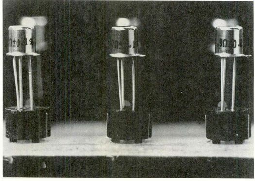
--- Tiny precision resistors are available now in transistor-style
packages that plug into transistor sockets. (Courtesy of Vishay Resistive
Systems)
Replacement resistor tips
Using a 1 W to replace a ½-W (or a 2-W to replace a 1-W) carbon-composition resistor is a good technique, but only in certain circuits. Generally, this kind of higher-wattage substitution is safe in audio, IF, video and the low-level stages of vertical and horizontal sweep.
Substitution of a larger size eases the tolerance requirements since the larger resistors run cooler (better conduction and radiation cooling) and they appear to be less prone to resistance variations not caused by overloads.
Of course, replacement of a carbon resistor with a metal type is usually an improvement without any drawbacks. However, keep in mind the possibility of higher inductive properties in the metal types.
The resistor selection becomes more critical in the horizontal-sweep circuits because of the strong pulse amplitudes and higher de voltages, such as boost, focus and high voltage.
Here is an extreme example.
Many older color-TV receivers had a small 66-M-o resistor that acted as a bleeder for the 5000-V focus supply. This calculates as a dissipation of only 0.38 W (less than half a watt). A technician decided to replace it with a 2-W carbon-composition resistor. However, these were available in values only up to 22- M-o, so three were used in series. Within a few weeks, the TV developed poor focus. The three resistors had a burned look, and each measured just a fraction of the rated resistance.
What could have gone wrong? A total of six watts was used (a 10 times safety factor). The technician had neglected the handy rule of not applying more than 700 Vdc/in. of the resistor body.
Each 2-W resistor was about 3/4-inch long, so it was rated (in the absence of specific data) at 525 Vdc. But each 22-Mo resistor was called on to withstand about 1700 V, which is more than a three times overvoltage.
Also, don't forget the change of resistance when carbon-composition resistors are subjected to heat cycles. A resistor with horizontal signal across it has 15,734 heat cycles/s. Practical experience has shown a higher-than-normal failure rate of resistors used in the plate circuit of horizontal-oscillator tubes. That's one area to examine if the picture lacks width on the right edge and the HV is a bit low.
For replacements up to 2-W sizes and where the original specifications are not known, it is best to stock only metal-film flame-proof resistors.
Of course, the gray overlays on schematics take precedent over all of these general suggestions. The components in those areas are important for improving safety and preventing fires. Therefore, use only manufacturer-recommended re placements, or duplicate the original specifications for all safety-area components.
Also see: RCA Flameproof Film Resistors