By Robert L. Goodman, CET
Repairs of intermittent conditions can be made easier by these examples and technical tips from an experienced technician.
Most electronic technicians detest trying to locate the causes of intermittent troubles in the equipment they service. Troubleshooting symptoms of erratic operation can be trying and it demands the utmost in knowledge and testing skills.
The proper choice of testing methods plus factual records of similar defects and their solutions can be very helpful. That is the purpose of these case histories about known repetitive failures and unique problems.
It doesn't always start
If the sound and picture began operation when the TV was turned on, it would continue working until turned off. But perhaps the next time power was applied, there would be no sound, no raster, an unlighted dial lamp and no voltage in several dc power sources.
In this General Electric YA chassis, most of the dc-voltage supplies are produced by scan rectification of horizontal-sweep power. Even the channel-selector lamp is powered by horizontal sweep.
The usual cause of failure to start at turn-on is a horizontal oscillator that doesn't oscillate. One module contains the entire circuit and it can be replaced to test for that possibility.
Horizontal oscillator--The module can be repaired if desired. Figure 1 shows the oscillator and multivibrator circuits. Dc voltage from the phase detector varies the bias of Q550; and the Miller Effect capacitance change operates to vary the oscillator frequency as needed for horizontal locking. Q550 parallels the oscillator coil, L550.
The Q555 transistor operates in a modified Hartley oscillator, with the collector and base coupling capacitor connected to out-of-phase ends of the tapped oscillator coil. This type of oscillator has more than enough feedback and therefore, should start dependably. If it does not, some component probably has a marginal defect. A weak oscillator will tend to be erratic about starting.
One handy measure of oscillation strength is the base-to-emitter voltage. Photofact 1496-1 shows base and emitter voltages that calculate to-0.9 V of bias. For an NPN transistor, this is reverse bias.
Stronger oscillation would increase the negative bias (decrease the positive voltage at the base) and weaker oscillation reverses that action.
Check the oscillator and multivibrator stages with a scope when the TV is working normally. Then when it fails to start up, check the same points again, noticing where the signal stops.
The components that cause erratic starting most often are the Q550 and Q555 transistors, C556 and L550. Be alert for bad solder connections and hairline cracks in the circuit board.
Monostable multivibrator---Transistors Q560 and Q570 comprise the monostable multivibrator of Figure 1. That kind of multivibrator does not oscillate. One of the two possible states is stable and the other is not. When Q560 is triggered by an oscillator pulse at the base, the multivibrator goes through one cycle and then stops until triggered, again. The value of a monostable multivibrator (sometimes called a Schmitt Trigger) is in the precise pulse widths that can be obtained.
For proper operation of the horizontal-output stage, the width of pulses at the base of the Q920 horizontal buffer must not vary by more than 10% from the standard.
Picture width and horizontal linearity can be inadequate and the horizontal-output transistor can fail often if the pulse width is wrong.
Intermittent operation is caused usually by Q560, Q570, diode Y560, capacitor C562 and the L570 choke.
Intermittent height
The partial schematic in Figure 2 is typical of the vertical-sweep circuit in many of the older Zeniths (this one is chassis 16Z7C17 of Photofact 1105-3).
Many intermittent problems can be traced to the setup switch, which eliminates the vertical sweep at one position by opening the short across R253, the cathode resistor. Picture bending and shaded rasters some times are caused by leakage in the same switch. Both video and some vertical waveforms are routed through the various sections. Test for an open switch by shorting across R253.
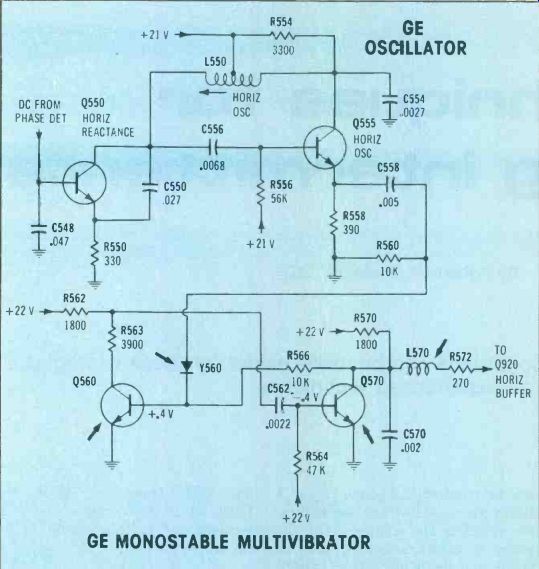
Figure 1---The horizontal oscillator in the GE YA chassis is followed
by a monostable multivibrator which provides a constant pulse width to
drive the horizontal-buffer transistor. GE MONOSTABLE MULTIVIBRATOR
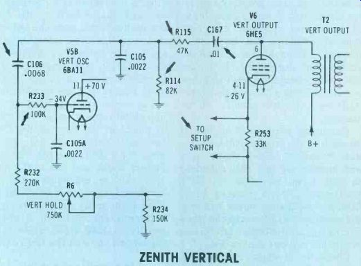
Figure 2---Components in the positive-feedback loop of the Zenith tube-type
vertical-sweep circuit cause many of the intermittent problems. Those
marked with arrows are the first suspects. ZENITH VERTICAL.
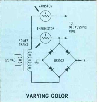
Figure 3--Symmetrical ac current of the main full-wave bridge is used
for automatic degaussing. At turn-on, the thermistor has about 120-ohm
of resistance. A large voltage drop is produced by the capacitor-charging
current. This higher voltage causes a low resistance in the varistor
which passes a strong current to the degaussing coil. The thermistor
wattage produces internal heat which forces the resistance to decrease.
This de creases the thermistor voltage drop and lower voltage is applied
to the varistor. The lower voltage increases the varistor resistance,
which reduces the degaussing current. These conditions continue until
the thermistor is nearly a dead short and the high varistor resistance
blocks the degaussing current. The varistor, the thermistor and any of
the bridge diodes can cause wrong or intermit tent degaussing. VARYING
COLOR.
Other intermittent conditions originate in components of the positive-feedback network. R115 has produced many cases of wrong frequency or intermittent height. It should be replaced with one of higher wattage. Other suspects include C167, R114, C106 and R233.
Signal-injection tests--Problems in the positive-feedback network can be proven by testing the oscillator and output stages as plain amplifiers. Follow this sequence of tests:
Disconnect the R114 end of C 106.
If some sort of picture height remains on the picture tube screen, the vertical-sweep circuit has a parasitic oscillation in the absence of the positive-feedback pulses.
(Normal circuits have no height.) Check filter capacitors, components from oscillator plate to output grid, diodes around the oscillator cathode and the 15K resistor at pin 9.
Assemble two clip leads and a 0.1 µF capacitor for injection tests.
Connect this test capacitor from the 6.3 V heater supply to plate (pin 6) of the output tube, while watching the raster.
If the plate has dc voltage and the yoke and output transformer are alright, the horizontal line (from the lack of vertical) should move downward and back to the center in a fast blink. A very small amount of deflection should be seen.
Move the capacitor lead to the vertical output grid pin 2. About 3 to 5 inches of vertical height should be seen if all downstream components are good. Linearity will be poor.
With the test capacitor moved to the oscillator plate (pin 11) the height should be identical to the previous test. If not, the coupling capacitor is bad.
Connect the test capacitor to the pin 10 oscillator grid. If the tubes and amplifying components of both stages are not defective, the picture should have almost full height (perhaps with poor linearity).
Move the test capacitor to the disconnected end of C106. The height should be slightly less than during the previous step.
If the last step provided almost full height, the amplifier path of the vertical circuit has been checked and found to be alright. Therefore the problem of lack of height must be in the positive-feedback path.
Intermittent purity
At random periods the color hues would vary. An intermittent in the automatic degaussing circuit was suspected. A test with only the red gun turned on verified the diagnosis. The degaussing was going into and, out of operation.
The Figure 3 circuit is typical of many, particularly RCA's. An intermittently open individual diode in the bridge or a defective thermistor is the likely cause of the erratic degaussing. These thermistors operate at a high temperature and often crack or develop a loose lead wire.
Also, check the Figure 3 circuit etched wiring for erratic connections.
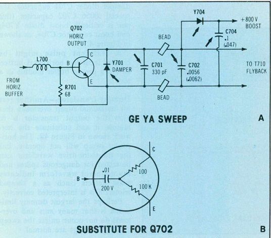
Figure 4 Those components marked with arrows are likely to have arcs
that can ruin the horizontal-output transistor. GE YA SWEEP; SUBSTITUTE
FOR G702
Zaps output transistors
A General Electric color TV (YA chassis) occasionally would blow the horizontal-output transistor when the power first was applied. An intermittent arc was suspected, since the performance was normal at all other times.
The difficulty with testing for such arcs is that a large number of expensive output transistors can be ruined during the unsuccessful tests.
One partial solution is to reduce the input line voltage by means of a variable transformer set for about 75 or 80 V. Or a 100 W light bulb can be temporarily connected in series with one side of the line voltage. The bulb gives a visual indication of current. When there is no overload, the bulb is lit with partial brilliance. If an overload occurs, the brightness goes to maximum.
After the bulb is connected, watch specific areas of the horizontal-sweep circuit and around the picture tube. Look for arcs or smoke each time the power is applied.
If the defect can't be located within a reasonable length of time, replace these components: Y701 damper diode; C701 capacitor; the special .0056 C702 capacitor (this one is critical); boost diode Y704; and boost capacitor C704, as shown in Figure 4.
A transient pulse might be coming from the horizontal buffer.
Install a proven buffer module as a test.
Dummy transistor---Another test for horizontal-sweep overloads that blow the output transistor is to remove it and substitute the net work shown in Figure 4B. The horizontal sweep will not operate, but the transistor-drive waveform can be tested for dangerous spikes and the collector waveform indicates some defects (such as a shorted tripler) if it is interpreted correctly.
Perhaps the largest dummy limitation is that many arcs and over loads do not occur unless the sweep and high voltage are normal.
Slowly drifting horizontal If the horizontal hold of the 25DC57 Zenith was adjusted for good locking when it was first turned on, the picture gradually drifted into the slanted lines of wrong oscillator frequency. Or if the hold was adjusted correctly after it was warm, the horizontal was out-of-lock next time power was applied.
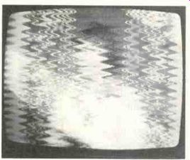
Figure 5---This "E" chassis Zenith intermittently showed a
frequency "hunting" pattern
on the screen.
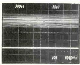
Figure 7 When C258 of Figure 6 was open, the B + at terminal T7 had
the large amount of hash shown by the top trace. After a new capacitor
was installed, the ripple and hash were gone (bottom trace).

Figure 8 In the "E" and "F" chassis Zenith TVs,
these are the points and components to check for sources of intermittent
height. VERTICAL COLLAPSE; 9-92 VERTICAL
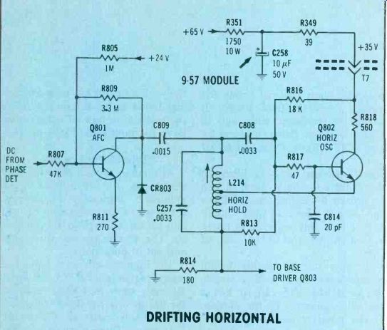
Figure 6 Drifting horizontal frequency in the Zenith 25DC57 was caused
by an intermittently open capacitor (C258) that was mounted externally
to the module. DRIFTING HORIZONTAL
At other times, the picture would have a violent "hunting" pattern (see Figure 5) that resulted from overcorrection of the frequency error. These various symptoms were intermittent and at other times the operation was normal.
The AFC and oscillator circuits were on the 9-57 module; therefore, the module was replaced. However, the troubles continued erratically.
The search was widened to include the B+ sources and the horizontal components not on the module (schematic in Figure 6).
Nothing wrong was found until module terminal T7 was scoped.
Hash was present there (top wave form of Figure 7) at times. When the problem disappeared on its own, the hash was gone, as shown by the lower scope trace.
Paralleling a new 10 uF capacitor across C258 stopped the problem, and it was soldered into place after the old one was removed. There was no horizontal drift following the capacitor replacement.
Causes of similar horizontal drift have been traced to the L214 oscillator coil (which also is the hold control) or to C257, the .0033 pF tuning capacitor for the oscillator coil.
Intermittent vertical sweep A picture that collapsed to a narrow horizontal line was a problem that occurred several times in various chassis of the "E" and "F" Zenith color receivers. Sometimes the line then would black out because of the safety circuit action that applies cutoff bias to the picture tube whenever there is no vertical sweep. The 0.6 A vertical fuse also might blow.
Vertical sweep in these modular TVs requires one-35 V supply and one +35 V supply. Figure 8 shows the yoke terminals and dc supply terminals of the vertical module.
Either bad filter capacitors or intermittent opens at the U2 and W3 pins can cause these intermit tent symptoms. Carefully check the back side of the chassis where terminals are inserted, and resolder any suspicious-looking joints.
Scope the +35 V and -35 V supplies at U2 and W3 for excessive ripple or hash. If abnormal amplitudes are found, check for an open C216 or C218 filter capacitor.
If the filters or the terminals become intermittent for very long, the ripple and hash will ruin the yoke or blow the 0.6 A fuse. Some times one of the power output transistors is damaged also.
General tips
The only difference between a regular defect and intermittent trouble is that the intermittent problem has symptoms only at certain times. If the intermittent can be made to malfunction constantly, the cause can be found by conventional methods.
Some intermittent problems can be triggered by vibration, shock or temperature changes. Therefore, they all should be tried in an attempt to control the intermittent.
These are some techniques to try:
Use a variable line-voltage transformer to supply 10 V above or 10 V below the rating. Experiment to determine if there is a critical voltage.
Flex the circuit boards and their connectors. If moving the entire board promotes some disturbance, check, clean or tighten the plug-in springs and connectors.
Tap gently at specific components on the suspected module. Pry with a non-metallic rod or screw driver.
Heat the suspected area with an infra-red lamp or heated blower.
Don't use excessive heat; it's not necessary and it might cause damage.
Canned coolant should be sprayed carefully and selectively on components in the suspected area. Vary the amount of cooling; often only a small decrease of temperature is best.
After the problem area has been pinpointed, use a strong light and a magnifier to locate small cracks in solder connections or board wiring.
A crack that can't be seen with the unaided eye can open a circuit or cause an intermittent connection. A circular crack around a pin or an eyelet is the source of many erratic problems. After the joint is soldered and repaired, look at it again with the magnifier. Some joints do not tin properly, and extra care must be used.
Use any or all of these techniques to control the beginning or ending of the intermittent period. After the symptoms can be controlled, the actual defect can be found with no more than the usual trouble.
Also see: A meter that lied