Here is an effective new method of identifying and removing interference coming from modulated RF carriers in audio amplifiers.
By Wayne Lemons, CET
Side effects of radio frequency pollution often take many different forms. Symptoms range from intermittent interference lines on certain TV channels to the audio of CB transmitters that is heard over public-address systems.
One reason for the variety of symptoms is that the interferences can enter the equipment either through the RF/IF section or through the audio stages. The techniques for eliminating these two basic kinds of interference are very different.
Therefore, the unusual testing system described here applies only to accidentally detected audio that travels through audio amplifiers.
Demodulated audio
When modulated RF of sufficient amplitude enters an audio amplifier, the high level can drive a tube or transistor into a nonlinear part of the operating curve. This non-linearity' demodulates the carrier and produces audio from the original modulation. After this audio is formed and added to the desired audio in the amplifier, it cannot be eliminated. The only solution is to prevent the demodulation.
The cure, therefore, is to reduce the level of the modulated carrier until it is too weak to cause accidental detection. RF signals cannot be heard, so there is no problem so long as the RF carrier is not detected.
Bypassing the RF
Eliminating RF from an audio stage appears to be very simple. Just bypass the RF with a capacitor of small value that will not affect the normal audio. Although the idea seems plausible, the added capacitor seldom helps enough, and often makes the interference worse.
High-frequency signals are not likely to enter at the audio-input terminals. Most inputs have shielded cables and wiring which should act as a bypass capacitor.
Additionally, many amplifiers have 100pF to 330pF fixed capacitors connected directly across the inputs.
These interfering carriers use the power cables, speaker wires, any other unshielded wires or even the metal braid of the shielded wires to enter the amplifier wiring. Such wires act as antennas to bring the RF signals near the amplifier stages.
Next, the unwanted RF signals use the chassis or a ground loop of the board wiring to flood the amplifier with a strong RF level.
Although the RF can reach a susceptible transistor input by stray capacitances of the wiring, it may travel through other hidden paths.
Amplifier wiring has many unsuspected impedances and resonances to RF frequencies which couple and even amplify the RF. When such strong carriers reach a transistor base, demodulation can occur.
The top scope trace is typical of modulated RF carriers that are de modulated to audio (bottom trace) by nonlinearity in amplifiers.
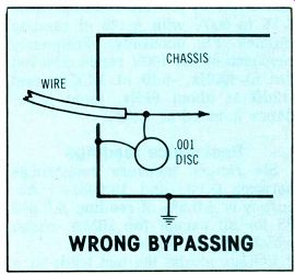
Figure 1---Bypassing RF inside the shielded chassis can form a loop
to couple the RF from the wire to the circuit wiring.
Wrong bypassing
An incorrectly connected bypass capacitor can increase interference, as shown in Figure 1. The internal capacitor forms a loop to couple the RF on the wire inside the chassis, and the loop acts as an antenna to radiate the RF energy.
The better way of bypassing any wire that enters the shielded chassis is to use a feedthrough capacitor or connect a conventional capacitor outside the chassis (see Figure 2).
Shielding and ground wires
One misconception is that a metal shield around an amplifier will prevent RF signals from entering. But shields are not absolutely necessary. In fact, the interfering signals might use the metal chassis as an injection loop.
Providing a true ground at these high frequencies is almost impossible. A chassis grounded to earth might be hot at some points and cold to RF at others. Also, a ground wire probably won't help because every wire with RF has hot and cold points at each quarter wave length. A random-length ground wire might even increase the interference.
RF impedances
As stated previously, the principal cause of demodulated interference in an audio amplifier is high impedances to RF (circuit resonances). These unintentionally tuned circuits can multiply the RF level by many times, and they are formed by the wiring versus the stray capacitances.
For example, a bypass capacitor from input plug to ground might act as a coupling capacitor from an RF-hot spot on the ground direct to the base. In other circuits, the shunt capacitors complete a resonant Pi network that takes a weak signal at low impedance and trans forms it to a stronger signal at high impedance.
The surprising discovery about resonances in audio amplifiers is that there are so many of them. A single input circuit might have several resonances between 10MHz and 220MHz or higher. Within this range, the resonance peaks can be either broad or sharp. Breaking up these resonances is the secret of eliminating audio-rectified interferences.
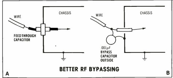
Figure 2 Here are two good methods of preventing RF from entering the
chassis on a wire. BETTER RF BYPASSING.
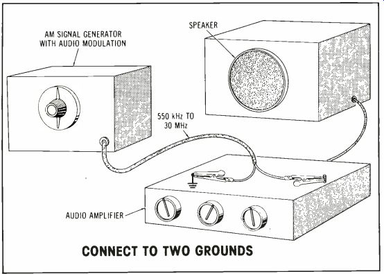
Figure 3 A modulated generator signal is connected to two widely separated
grounds of the amplifier. As the frequency is varied, the generator signal
activates the unplanned RF-resonant circuits so they can be swamped,
detuned or the RF removed from transistors by filtering. CONNECT TO TWO
GROUNDS
FM audio interference
Frequency-modulated (FM) signals often are demodulated in audio amplifiers by hidden tuned circuits and nonlinearity.' This seems impossible. Normal FM receivers must have elaborate demodulation circuits that operate by phase shift to produce audio. None of that is found in an audio amplifier.
However, there is a more simple kind of FM demodulation (called slope detection) where the signal moves up and down the skirt of a resonant circuit. Thus FM audio is recovered by conventional AM detection.
In audio amplifiers, the frequency slope is formed by the accidental tuned circuits, and the nonlinearity of an overloaded audio stage sup plies the AM detection. Both conditions are necessary for FM audio to be produced in an audio stage. The interference can be prevented by either swamping the resonances or reducing the nonlinearity (or both).
These fixes are based on practical experience. When I first announced a series of FM broadcasts, I was surprised and dismayed to find many record players, tape recorders and sound systems in the vicinity would reproduce the audio. There fore, one of my extra jobs was to eliminate the interference.
Silent interference
Even more puzzling are the cases where FM carriers cause trouble without being heard. One such problem involved the background music and paging system in a supermarket. Intermittently the music would stop and no micro- phone paging could be done during that time. The 15s to 30s of paging silence was accompanied by a loud buzzing noise in the speakers. The store owner found that turning down the microphone gain would bring back the background music.
Evidently the problem originated in the microphone preamplifiers. How ever, the symptoms would not occur while I was there.
Finally, an observant grocery helper noticed that the problem always happened when a taxi came to a nearby taxi stand. The driver was asked to transmit with his 2-way FM radio as I listened to the store sound system. His broadcasts were the cause of the mysterious silences, but he was using the radio legally and had no responsibility.
So, this required elimination of the problem by modification of the microphone preamplifiers. The method described next provided the cure.
Tracking down interference
Debugging radio-frequency interference (RFI) raises many questions and calls for many decisions. Can the circuit modifications be made in an electronic shop, or must the offending transmitter be used as a source while the audio system is in the usual position? How can a technician be certain the RFI is eliminated?
In order to answer those questions for myself, I discovered (al most by accident) a system of debugging that is almost infallible.
The only item of equipment is an AM signal generator of any quality.
Those with rough and distorted signals are excellent, so long as the RF output and modulation are very high. The generator applies many frequencies to the amplifier as the testing proceeds.
Create an RF loop
As shown in Figure 3, the generator is attached so the signal travels from ground to ground across the chassis or circuit board.
Do not connect the generator signal to the amplifier input or inputs.
Allow the input terminals to float.
If the amplifier has provisions for a speaker, connect a test speaker. If not, connect the preamplifier (or tape deck) to a signal tracer or power amplifier that in turn drives a speaker. The object is to listen to the audio coming from the problem amplifier or preamp.
Turn the generator RF output and modulation to maximum. Turn one channel to maximum gain on the amplifier being tested. Rotate the generator dial from one end to the other of all bands and listen for the audio tone. Any amplifier that is susceptible to radio interference will produce a generator tone at several different frequencies. Probably some frequencies will have a louder tone.
CB interference
If the complaint involves CB radios, tune carefully through the 27MHz to 28MHz band. Any tone that's heard indicates the amplifier probably will reproduce CB audio.
Next step is to stop the audio rectification. From this point, some trial and error experimentation is in order, for there are no absolute answers.
Generally, the first or second audio transistors are prime suspects. These usually operate at full gain without any control between them and the input terminals. Test by listening to the tone as the amplifier gain control (downstream from the suspected stage) is turned to zero. If turning down the control eliminates the tone, the source of the audio rectification is ahead of the control.
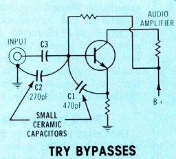
Figure 4 First tack solder ceramic capacitors (having very short leads)
to these points of the first preamplifier transistor. Unless the RF interference
is worse with them connected, leave them there.
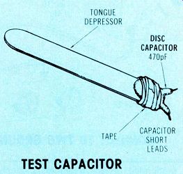
Figure 5 Don't hold a capacitor while temporarily connecting it. Instead,
tape the capacitor to an insulator (such as a tongue depressor).
Try bypasses first
After the principal frequency of the rectification is located, try connecting a 470pF ceramic capacitor with very short leads between base and emitter of the input transistor, as shown in Figure 4.
Tack solder the leads in place. Do not touch the capacitor; a hand can act as an antenna.
A capacitor can be mounted to a wooden or plastic tongue depressor (Figure 5) to speed up these tests.
If the 470pF ceramic did not make the tone louder, leave it in place and try a 270pF ceramic from base to ground (or from emitter to ground if the input is at the emitter). Try grounding the capacitor to various ground points within reach. If a spot can be found that radically reduces the interference tone, solder the capacitor there.
Next, leave those capacitors in place and cut the transistor input wire (base or emitter according to the input). As shown in Figure 6, bridge the cut with a 390Q resistor for the grid circuit (or a 39 ohm value if in the emitter circuit). To check for more RF reduction, disconnect the previously installed capacitors, one by one. Unless the interference is reduced by removing one or both capacitors, leave them in place.
Also, try moving the 270pF capacitor to the side of the added 39 ohm or 390 ohm resistor that is toward the input terminals while leaving the other capacitors in place (Figure 7).
If the RF interference remains excessive, try a 470pF capacitor from the first transistor collector to ground. Any improvement indicates the problem is at the base circuit of the second stage. Try the same tests as detailed for the first stage.
A small-value unbypassed resistor added to the emitter circuit (Figure 8) might reduce the RF interference. Try a 0.01 uF ceramic from the B+ (or B-) supply to ground. If the power line enters the chassis, try bypasses as shown in Figure 9. (In one stubborn case it helped to operated a preamp from batteries.)
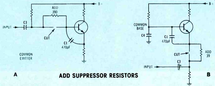
Figure 6---If the bypass capacitors do not eliminate enough of the audio
rectification, cut the wiring as shown and add parasitic-suppressor resistors.
ADD SUPPRESSOR RESISTORS
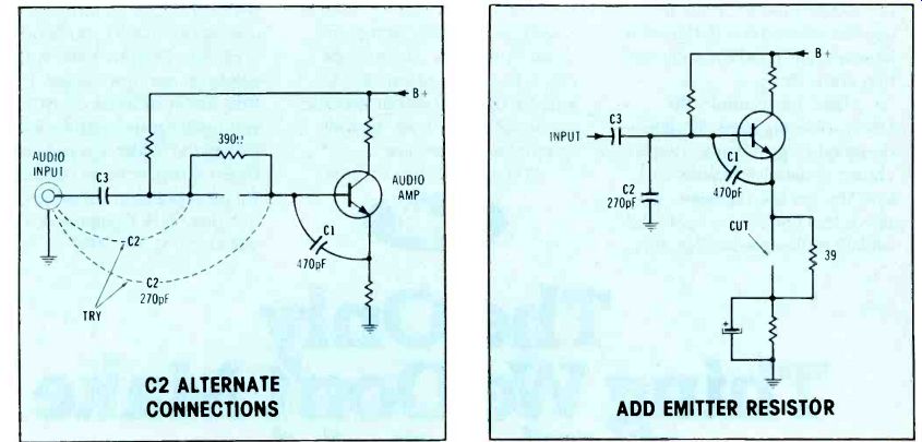
Figure 7---Test alternate connections of C2 and choose the one giving
the least audio demodulation.

Figure 8 An unbypassed small-value resistor added to the emitter circuit
might reduce the RF interference.
Persevere
If the RF interference has not been eliminated by now, the amplifier has a stubborn problem. But there are more things to try.
Modify the input wiring by cutting and removing the input wire right at the transistor base. Run a separate short wire direct to the input capacitor. If the wire is more than an inch long, shield it. If a shielded wire is used, ground it at only one end, trying each end for the best result. Or ground both ends at separate points. Sometimes a different or smaller input coupling capacitor will reduce the interference. If it is an electrolytic type, make certain it is not leaky.
Ground the input terminal; if the collector de voltage changes and holds the different reading, the capacitor is leaky.
What about RF chokes? RF chokes should be used only as a last resort. The inductance can resonate with stray capacitance and create a new resonance. For example, I once completely removed CB interference from an amplifier by using chokes, only to find the amplifier now received the local FM station! The Figure 10 circuit suppressed RF rectification in a Bogen pre amplifier that handled low-impedance microphones. The chokes were VHF types wound on ferrite cores. Addition of a 330 ohm 1/4W carbon resistor across each choke might be necessary to break up other resonant points.
Final tests
After the amplifier seems to have an acceptable level of RF interference, again use full generator output and sweep through all available frequencies. If no frequencies can be heard very loudly, the amplifier is ready for the ultimate test. Hold a 2W or 3W CB walkie-talkie with the antenna near the amplifier wiring and press the transmit button. There should be no acoustic feedback and the CB audio should not be heard in the amplifier speaker.
After the amplifier is reinstalled in its regular location, repeat the test with the CB walkie-talkie. If the amplifier can withstand this severe test, it should keep out all unwanted RF signals.
Summary
The secret of eliminating the demodulation of RF in any audio amplifier is in breaking up all RF resonances and hot spots by bypass detuning, with parasitic-suppressing resistors or by rerouting and re dressing the wiring of sensitive input stages.
Use of an RF generator to monitor the effectiveness of each fix gives assurance that the interference will still be missing after the amplifier is delivered.
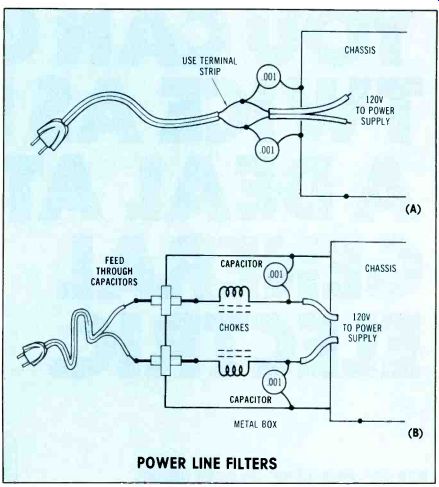
Figure 9---These two methods are recommended for preventing RF on the
line-voltage cable from entering the chassis. POWER LINE FILTERS
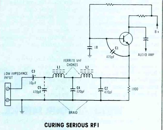
Figure 10---A stubborn case of RF interference required this elaborate
filtering of the low-impedance input to the transistor emitter. If the
chokes cause serious resonances at other frequencies, parallel them with
3300 carbon resistors. CURING SERIOUS RFI
Also see: