Although no tube-type color TVs have been manufactured for several years, about half of the bench repairs now involve these older models, according to many shop owners. Therefore, these service techniques are for tube-equipped TV models.
By Homer L. Davidson
More component failures occur in the horizontal-sweep section than in all other color-TV circuits combined. Most of the power of a TV is used there, which increases the number and seriousness of the parts' defects. Problems are compounded by the high-voltage circuit, which is included with the horizontal deflection.
A good sequence of tests is absolutely necessary if a technician is to locate the source of trouble in the shortest time. Such logical methods should include waveform analysis, ac and dc voltage measurements, and other instrument tests after the preliminary steps and before replacement of any parts that are suspected without proof.
Which testing sequence? Horizontal-sweep and high-voltage problems can occur in so many different ways and exhibit such a variety of symptoms that an all-inclusive list of tests should not be followed completely in all cases. For example, tests for frequency drift usually would not require many of the visual steps. However, those preliminary steps are vitally import ant in cases of missing raster.
Also, fewer instrument tests are required when important clues can be seen on the raster. And more instrument tests should be per formed when there is no raster and picture.
Therefore, you would not be expected to do all steps in the suggested sequence that follows. Instead, begin at a point that's appropriate for the symptoms.
Visual and preliminary steps For cases of intermittent noise lines, missing raster and picture, excessive replacement of horizontal-output tubes, raster blooming, or a narrow picture, perform this list of preliminary tests:
Look for missing tubes and tubes with cracked glass or loose plate caps and connectors.
With power turned on, look for any tube showing internal arcs, those showing a gassy ionized glow.
Blue glow on the inside of the glass envelope is merely fluorescence. It is harmless and should be ignored.
A blue glow between plate and cathode indicates gas, and the tube should be replaced.
Gently tap the horizontal tubes with a plastic rod or the handle of an insulated screwdriver. Replace any tube showing internal arcs.
After the power has been applied for two to three minutes, carefully examine the damper and horizontal-output tubes for any red areas on the metal plate. A tube with a red plate either is bad or there is an overload in the circuit at input or output. Try a new tube as a test, but don't let it show a red plate for more than a few seconds, because it might be ruined.
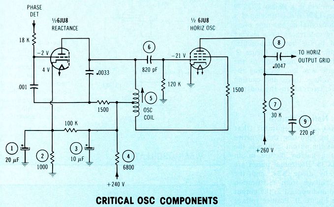
Figure 1 These are the reactance and horizontal-oscillator components
that should be tested first in the Admiral 6H10 Photofact 1113-1). An
open #1 capacitor causes soft locking, resistor #2 burns when the tube
shorts, an open #3 capacitor weakens the output-grid drive, #5 oscillator
coil can become intermittent from bad soldering, leakage in #6 coupling
capacitor changes the frequency, reduced values of #7 resistor can shorten
the output tube life, a leaky #8 coupling capacitor also ruins output
tubes, and the resistance and capacitor values of #9 waveshaping can
affect frequency.... CRITICAL OSC COMPONENTS
If none of the previous tests aroused suspicion, test all horizontal-sweep tubes including oscillator, output, damper, HV and focus rectifiers, and regulator (if used).
Replace any bad ones.
Assuming that no raster has been obtained to this point, the high voltage should be checked at the picture tube. Normal HV but no raster indicates the horizontal deflection is alright but the picture tube is bad or a chassis defect is preventing it from conducting the HV and showing a raster.
If the HV is normal but there is no raster, the dc voltages at the picture tube socket should be checked against the schematic. Low G2 screen voltages, low control grid voltages, or high cathode voltages can eliminate the raster. Wrong grid voltages point to a problem in the chroma circuit, and high cathode voltages indicate a video defect. Loss of focus voltage or heater voltage also kills the raster.
But when there is no high voltage, measure the grid and screen voltages of the horizontal-output tube. Judge them by schematic voltages.
A common shortcut is to measure the negative dc voltage at the out put control grid and then assume the oscillator signal is proper if this reading is within tolerance. How ever, an oscillator signal about double in frequency kills the HV while providing the correct negative voltage. Also, dc voltages can reach the grid from outside sources, thus giving wrong dc voltages when the oscillator signal is normal. A distorted waveform from the oscillator can provide the correct dc voltage but give wrong operation. It is best to measure with a scope the wave-shape, amplitude and frequency of the grid waveform. This removes the guesswork.
When the output or damper tube (or both) have a red area on the plate, a limited analysis of the source of trouble is possible. A red spot on a damper plate before the output turns red is caused either by loss of oscillator drive or by damper-circuit leakage. Such damper leakage does not allow the output plate to run red, but a loss of oscillator drive does. A red plate of the output tube (but none in the damper) indicates an excessive ac load at the plate of the output tube.
This can be a shorted or gassy HV rectifier, shorted turns in a pin cushion transformer or excessive current in a regulator tube. Excessive picture tube current will do the same, but the overload can be removed by unplugging the CRT socket.
A narrow picture and reduced high voltage can be caused by low oscillator-signal voltage at the out put grid by a weak output tube, a weak damper tube or low screen-grid voltage.
A defective HV regulator can kill the raster, cause blooming or produce a dim narrow picture.
Most regulators can be defeated easily to prove whether or not they are at fault. No damage occurs if the TV is not operated very long without the regulation. Removing the plate cap (watch out for arcs) works tine for 6BK4s, while pulse regulator tubes can be taken out of the socket (if the heaters are not in series). Varistor grid regulators can be defeated usually by disconnecting the horizontal pulses at the varistor. Check a schematic for the best method.
Total loss of oscillator signal at the output grid overloads the out put tube, causes a bright red plate and destroys the output tube within a few seconds. This probably is the principal cause of excessive output-tube failures.
Soft horizontal locking and horizontal-frequency drift usually originate in the horizontal phase-detector or the horizontal-oscillator stages.
Critical oscillator components
Figure 1 schematic shows the components of reactance stage and horizontal oscillator that should be checked first during any oscillator malfunction.
Insufficient drive
The problem in a Philco 22QT79 (Photofact 1239-3) that developed a ruined horizontal-output tube every few hours was traced to a leaking capacitor in the horizontal-oscillator circuit, as shown in Figure 2.
Signal from the oscillator to the output grid was low, reducing the negative voltage there, and causing excessive current in the output tube.
Narrow picture
An over-active regulator (that operates by adjusting the negative voltage at the output grid) was the cause of a narrow picture in an RCA CFC38. Horizontal pulses are rectified by diode X23, and the negative voltage from rectification is filtered and applied to the output grid (see Figure 3). Positive voltage from R170 cancels the regulator negative voltage at high brightness.
But at low brightness, the diode pulse amplitude and rectified negative voltage increase. This increase of negative grid voltage reduces the maximum 6LQ6 plate current and decreases the high voltage.
In this case the grid bias was about-75V.

------------ Figure 2 In a Philco 22QT79 (Photofact 1239-3), leakage
in the .0033 uF oscillator-tuning capacitor decreased the oscillator
output amplitude. This reduced drive at the output grid increased the
dissipation so the output tube failed regularly after just a few hours
of operation.
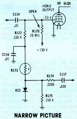
Figure 3 A narrow picture on the screen of a CTC38 RCA was produced
by too much HV regulation. R170 is included to add some positive voltage
to the output grid where it cancels excess negative voltage from varistor
rectification. When R170 opened, the output grid was excessively negative,
thus giving the effect of a weak tube.

Figure 4 The Penncrest's dim narrow picture directed attention to the
low boost voltage.
Subsequent testing around the flyback and damper finally located severe leakage in C115, the .047uF boost capacitor.
------------------

Figure 5 Bad capacitors in the damper circuit can kill the high voltage,
narrow the picture or distort the linearity. The A circuit had poor linearity
and excessive output plate current because the .0022pF capacitor was
nearly shorted. No HV was present in the B circuit when C120 shorted.
DAMPER CAPACITORS
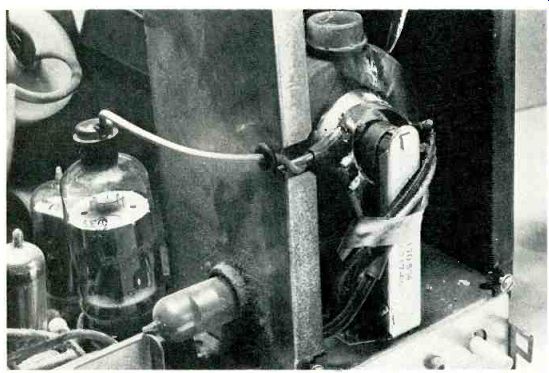
Figure 6 An arc burned a path down the HV coil of the flyback. This
overloaded the output tube, causing a red plate. Dampers don't have red
plates, but output tubes do, when serious overloads occur in the flyback
area of the output stage.
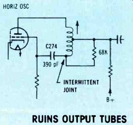
Figure 7 After the horizontal oscillator stops working, the horizontal-output
tube will be ruined within a few seconds.
An intermittent C274 often is the cause. However, in this case, a connection was intermittently open at the end of the oscillator coil. Use a silver-mica type to replace C274. The temperature coefficient of most other types produces excessive drifting and erratic locking.
Boost problem
A dim picture and a slightly narrowed picture were the symptoms of a Penncrest TV. Although drive at the output grid was low, the most significant clue was the insufficient boost voltage. Changing capacitor C115 (Figure 4) cured the problems.
Damper capacitors
Shorted damper capacitors eliminate all high voltage, and leaky damper capacitors often narrow. the picture and distort the linearity (see Figure 5).
One lead of each capacitor should be removed for an accurate leakage test. Use only good quality capacitors for replacement of any had ones.
A quick test for a shorted damper capacitor is to operate the TV without a damper tube. If careful adjustment of brightness brings a dim picture with foldover, it is certain a short somewhere is in parallel with the damper tube.
These damper capacitors are usually the cause of the short.
Shorted damper tubes and capacitors often overheat the horizontal output tube and cause red areas on the plate. However, other bad plate loads, such as the carbonized path of the flyback in Figure 6, also kill the high voltage and cause a red plate.
Intermittent oscillator
Any moderate overload of the horizontal-output tube will ruin it.
Such overload conditions usually cause these failures at regular intervals. Drive and cathode current of the output tube are the important tests for those symptoms.
However, failure of the output tube at very irregular intervals after careful tests have shown no steady overload are caused most often by an intermittent horizontal oscillator.
No other defect ruins an output tube quicker.
There are two general causes of an intermittent oscillator. One is that sometimes does not start when the TV is turned on. Suspect that cause if the receiver fails to light up, but works dependably otherwise.
The other basic defect is an intermittent in the oscillator circuit, such as a hairline crack in the circuit board or an intermittent component. Alternate applications of heat and coolant spray help locate erratic components.
Other unsuspected sources are loose contacts in the tube socket or a bad ground at the oscillator tube's heater pin.
Figure 7 shows the troublemaker in one RCA CTC39. A bad soldered joint at the C274 end of the oscillator coil would open some times. Of course, this stopped the oscillation completely.
To reduce the number of ruined output tubes while you search for the cause of intermittent oscillation, monitor the output grid with scope or dc meter. Turn off the TV power within seconds after the monitor shows lack of drive to the output grid.
Excessive high voltage
A previous example showed how too much regulation could reduce both the width and high voltage.
The opposite is true also. A lack of regulation can increase high voltage during times of dark scenes (the extra width is not noticeable).
For normal picture brightness, the Figure 8 circuit should balance the negative voltage (from pulse rectification by the two varistors) against a positive voltage coming from the high-voltage control (R113). At those times, the regulator circuit essentially does nothing; the negative and positive voltages are equal.
When the screen goes dark, the HV and width increase, if there is no regulation. But the regulation varistors receive higher pulse amplitude and they produce a higher negative voltage which exceeds the positive voltage from the HV control. This increases the negative output grid voltage and the width and HV are reduced.
Therefore, any defect that eliminates the variable negative voltage causes excessive high voltage. In fact, the HV is higher than it would be without regulation (that is, with the bottom end of R108 grounded).
An open in C106, R109, varistors V110 or V111 can produce excessive HV without regulation.
Arcing
All metal connections or soldered joints around high voltage should have rounded corners to prevent HV arcs. As shown in Figure 9, apply a silicone-rubber seal over each flyback or HV-rectifier-socket connection.
Many of the older Zeniths had a 1500 ohm resistor at the HV tube socket. It was wired in series with the HV to the picture tube. These resistors often become erratic and cause noise lines in the picture.
Watch out for loose or corroded plate caps on output or HV tubes.
They too can radiate noise.
Comments
These methods and hints should help technicians troubleshoot horizontal-sweep problems in less time.
Remember, use visual and short-cut methods first, but follow them with instrument readings to identify the difficult repairs.
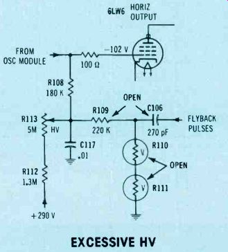
Figure 8 Excessive width and high voltage in the Zenith can be produced
by any open circuit that removes the negative voltage that's produced
by varistor rectification of horizontal pulses. The most common opens
have been in R109, C106 and one or both of the varistors, R110 and R111.
EXCESSIVE HV
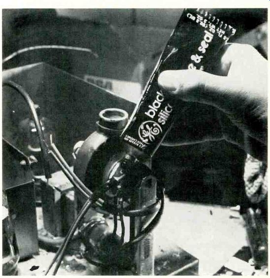
Figure 9 When sweep and HV components are replaced, make sure the soldered
joints have smooth rounded tips. Then cover each joint with silicone-rubber
sealant.
Also see: Hitachi dual-trace oscilloscope