
By Joseph J. Carr, CET
The terms standing waves, standing wave ratio (SWR) and voltage standing-wave ratio (VSWR) are used constantly regarding antennas, coaxial cable and radio/TV transmitters. Unfortunately, there is much confusion about the importance and measurement of standing waves. Even the name is not informative. Does it imply that other waves sit, lie down or run? A lack of basic understanding about standing waves can lead to misuse of excellent VSWR meters so they might produce wrong readings under some conditions. The material in this article is intended to help technicians avoid such pitfalls.
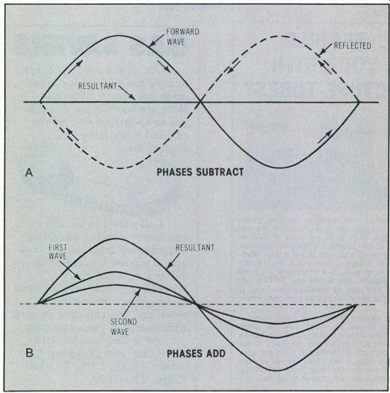
Figure 1 (A) When the forward wave and the reflected wave happen to
be at 180° relative phase, subtraction occurs. If both have the same
amplitude, cancellation takes place. (B) At anti-nodal points, both signals
have the same phase, so the amplitudes add.
Standing-wave model
Complex subjects can be understood more rapidly when they are compared to other already-known concepts. Hydraulic water flow is used often to illustrate electron current in basic circuits.
A model of standing waves can be the undulations in a length of rope. The rope is fastened at one end to a solid wall while the other end is moved up and down in various ways. It's easy to see the waves travel smoothly down the rope to the wall, apparently strike the wall and rebound at reduced amplitude and opposite phase back to the source. This is essentially the same as applying pulses or continuous waves to a section of radio transmission line or cable.
A continuous radio carrier moves downstream along a length of coaxial cable while any of the same carrier that is reflected from the load moves in the opposite direction upstream. Therefore, the relative phase between them changes constantly.
At some points, the two signals are 180° out of phase, so cancellation takes place (Figure 1A). When the amplitudes are equal, total cancellation occurs, leaving zero voltage. Unequal amplitudes pro duce an intermediate signal amplitude by partial cancellation.
Amplitudes of in-phase signals add, thus making a resultant amplitude equal to the sum of both.
These alternate additions and subtractions produce stationary points of maximum and minimum amplitude (or nodes and antinodes) that are called standing waves.
Matching versus standing waves Figure 2A shows perfect matching of 50 ohm source, 50 ohm coaxial signal-transmission line and 50 ohm noninductive load. All of the for ward signal is absorbed by the load; none is reflected back towards the source. A graph of the nodes and antinodes for this one example shows only a straight line. Without a reflected signal, no standing waves are formed. The SWR then is a perfect 1:1 reading.
Any deviation from the ideal matching of source, transmission line, and load allows reflected signal, which produces the peaks and nulls of standing waves. A graph of these standing waves (Figure 2B) shows the nodes are separated by a half wavelength of the signal. (This is true also of the antinodes.) A shorted or open load is the worst possible example of mis matching. As illustrated in Figure 2C and Figure 2D, the SWR has the same high ratio with either a short or an open load. However, the phase is different by a quarter wavelength for the two conditions.
Measuring SWR
SWR can be measured with different degrees of accuracy at some point in the transmission line by comparing one of these conditions: forward versus reflected voltage; forward versus reflected cur rent; or forward versus reflected power.
VSWR tests by RMS power provide consistently accurate readings, but they are not fast or convenient. For example, if a Bird model 43 Thruline RF wattmeter is used to measure the forward and reversed powers, the VSWR must be calculated from the following formula:
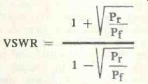
Of course, radio technicians soon learn the range of forward versus reversed power readings that indicate acceptable VSWR ratios, and therefore do not calculate each one.
The advantage of power SWR measurements is that testing at the transmitter, the antenna base or any other point in the coaxial cable gives the same dependable reading.
Most service-shop SWR meters compare forward and reversed voltage or current. However, these tests are sensitive to the location of the measuring equipment. In fact, they might mislead a technician into believing erroneously that VSWR can be reduced to 1:1 by trimming the length of the coaxial cable.

Figure 2--Mismatching of impedances produces the nodes and antinodes
of standing waves. (A) Perfect impedance matching eliminates all standing
waves. (B) The nodes are a half wavelength (of signal) apart. (C) and
(D) Although the standing waves have identical high amplitudes, a short
or an open at the antenna end of coax changes only the relative phase
of the antinodes (or nodes).

Figure 3--The voltage drops of forward and reversed signals are measured
in a resistance-bridge SWR tester.
These voltage or current VSWR meters do indicate relative VSWR, and so are useful for trimming the antenna length or tuning the matching circuit for minimum VSWR reading. But the 1.3:1 or 2.2:1 VSWR numbers obtained are not valid unless the measurement is made either at the base of the antenna or through a section of coaxial cable that is a multiple of the signal half wavelength.
For 27 MHz, a half-wavelength cable should be 14.6 feet long for foam type or 12 feet for regular.
Bridge VSWR meter
Figure 3 shows the schematic of a typical resistance-bridge type of VSWR meter. Two of the bridge arms are R1 and R3, and the bridge is balanced when the antenna impedance is exactly 51 ohm .
The switch is set to forward, the meter control is adjusted for full scale reading, then the switch is turned to reverse for the SWR reading from a special meter scale.
Monimatch meter
Two identical pick-up conductors are spaced the same distance from the center conductor of the internal transmission line in the monimatch type of SWR meter (Figure 4). RF current in the center conductor induces current in the pick-up wires and the signals are rectified by matched diodes to form dc voltages which are in proportion to the amplitudes of forward and reflected signals. With the switch set for forward, the calibrate control is adjusted for a full-scale reading.
After the switch is turned to reverse, the SWR is read from the calibrated meter scale.
Toroidal type
Basically, a toroidal-transformer VSWR indicator (Figure 5) operates similarly to the previous monimatch type. However, the doughnut-shaped current transformer is used instead of a pickup assembly.
RF wattmeters often employ a toroidal transformer, using the Ohms Law formula of wattage equals current squared divided by resistance. Capacitor values are chosen to provide accurate readings between 3MHz and 30MHz. This frequency compensation is not required for SWR readings because the meter is calibrated before each measurement.
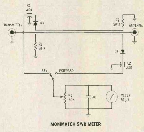
Figure 4 Monimatch SWR meters employ a transmission-line bridge.
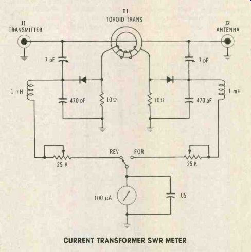
Figure 5 A toroid-type current transformer tests forward and reversed
current to measure the SWR.

Figure 6 Leader model LIM-870A tests antenna impedances between zero
and 1000 ohm.

Figure 7 (A) The Omega-T noise bridge tests antenna resonance. (B) Palomar
also markets a noise bridge with an extra control that can indicate whether
the antenna has a high or low resonant frequency. (C) This is a typical
noise-bridge circuit.
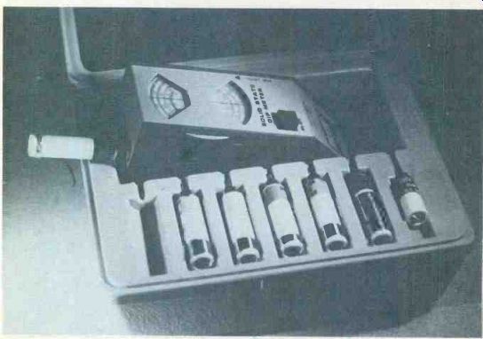
Figure 8 The Heath Solid-State Dip Meter can measure the approximate
tuned frequency of coils.
Other antenna instruments
Although many CB-radio technicians use only a SWR meter and perhaps an RF wattmeter, there are other antenna-testing instruments that can provide valuable information.
An antenna-impedance meter measures the resistive component of the antenna-feedpoint impedance.
One commercial model (Leader LIM-870A) is pictured in Figure 6.
It employs a variation of the standard ac Wheatstone bridge to measure between zero and 1000 ohm.
Another method of measuring antenna impedance is found in noise bridges of several brands (pictures and schematic in Figure 7). A noise bridge also is a type of Wheatstone bridge, but a wide-bandwidth noise signal is used instead of a sine wave. The noise is produced by a reverse-biased diode inside the meter, and is amplified before it is fed to the bridge. This is white noise, containing all frequencies (theoretically).
Operation of the noise bridge is simple, although it requires a receiver (preferably with an "S" meter) for the test-frequency band.
First, the bridge control is set for the coaxial-cable impedance (50 in most cases), and then the receiver is tuned slowly around the desired frequency until a dip or null of the noise level is noticed. This is the resonant frequency of the antenna.
Some models have an additional control to show whether the resonant frequency is up-band (Xi) or down-band (XC) from the desired one.
Approximate measurements of resonant frequency can be made with a dip meter (formerly a grid-dip meter, when tubes were used), which is an RF L/C variable-frequency oscillator having a plug in tank coil mounted externally, as shown in Figure 8. When the dip meter coil is placed near (and in line with) the coil that is being tested for resonant frequency, energy is transferred from one coil to the other. If both coils have the same resonant frequency, the test coil loads down the dip signal and reduces the meter reading.
Sweep tests with scope
Sweep tests can reveal the exact physical length of coax needed for any specific frequency. For example, the author used the equipment of Figure 9 to cut a coaxial cable for a certain 27MHz frequency.
A short at the load end of coax reflects a similar short to the input end when the cable length is precisely a half wavelength of the signal. Therefore, a dip in the sweep response curve shows the location of the half wavelength.
The coax was cut too long in the beginning. Next, the load end was shorted from shield to center wire, and the sweep/marker test was made to be sure the dip of the response curve was beyond the marker. One inch was clipped off and the sweep test made again.
This was continued until the response dip merged with the marker. Therefore, the coaxial cable electrical length was correct for producing accurate SWR tests at that frequency, regardless of the meter type used.
Summary and comments
Total elimination of standing waves can be accomplished only by perfect matching of source impedance, cable or transmission line impedance, and the non-inductive load impedance. Any less-than-perfect matching allows the signal to bounce from the load (or the source) and travel back through the cable in the wrong direction.
Relative phase between these forward and reversed signals produces stationary points of maxi mum amplitude (nodes from addition) and minimum amplitude (anti-nodes from subtraction). These maximum and minimum areas are called standing waves.
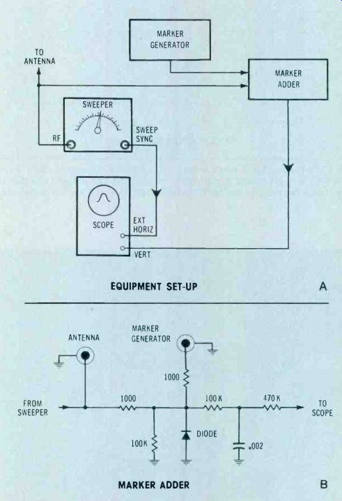
Figure 9 (A) This interconnection of equipment can show when coax is
a half wavelength. (B) A marker adder for post-injected markers is easy
to construct.
Notice that standing waves do not cause any reverse signal; instead, the direct and reversed signals produce standing waves.
However, standing waves in SWR units can be measured either directly according to the node and anti-node amplitudes or indirectly by the amount of forward and reversed signals. Measurements by RMS power are accurate when made anywhere in the coaxial/antenna system, while SWR measurements by voltage or current vary according to where the meter is connected.
TV ghosts--Excessive reversed signals (high VSWR ratio) reduce the total power radiated by the antenna in radio systems. Also, the reverse signal might be absorbed partially by the output stage, thus increasing the dissipation. But the bouncing signals cause other problems.
At the frequencies used by MATV and CATV systems, these reversed signals can cause an effect similar to location ghosts. So, correct matching of all such systems is much more important for obtaining sharp video pictures than for reducing transmission losses.
Also see: