With any electronics assembly and/or project construction, it is important that you understand how the various parts of the circuit work together and the objective of each component before you start gathering the components together and assembling them.
With any project that requires Integrated Circuits (ICs) or transistors, be careful to observe precautions about overheating their leads. If possible, use sockets designed for the IC chip required, instead of soldering directly into the chip's wire leads. If you don't have sockets available, be sure to protect the IC and/or transistor lead wires by using long-nose pliers as a "heat-sink" when soldering these leads.
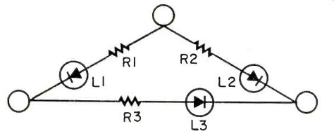
LED ELECTRICAL CIRCUIT TESTER
Typically, this kind of electrical power tester will use Neon lamps to indicate completed circuits or faulty circuits...why not LEDs? You can build this tester in a minimum of space. Wiring is simple but you must remember that you will be applying 120 volts to the circuit, therefore, it is prudent to encapsulate the completed circuit in silicone, such as caulking.
The "hot" lead will be a golden brass color, "neutral" will be chrome colored and the ground pin is u-shaped, usually with a green screw.
To test your device, plug it into a receptacle that you want to test. The receptacle is good if L1 and L2 light. If nothing lights, there is no power. Check for wiring errors or an open ground if some other combination of LEDs light.
This tester will trip GFCI outlets if used to test them, since the LEDs draw more than 6mA through the ground.
PARTS LIST FOR LED ELECTRICAL CIRCUIT TESTER
R1, R2, R3-15K ohm, 2 watt resistors.
L1, L2--Green LEDs.
L3-Red LED.
Misc.-Suitable enclosure.
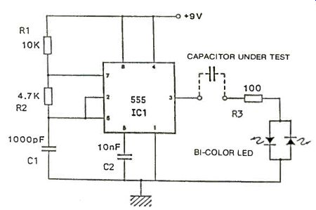
FUNCTIONAL CAPACITANCE VERIFIER
There are often situations in which a capacitor needs to be checked in order to ascertain whether it is functioning or not. The circuit shown here gives a quick indication of the condition of the capacitor, by using its most basic property i.e. the ability to block do voltages. The ubiquitous 555 timer is used to provide a train of non critical positive pulses. These pulses pass through the device under test, onto a bi-color LED sensor. In case of difficulties locating this LED, two standard separate LED's are fine. The pulse characteristics appearing across the dual LED are interpreted as follows:
1) Capacitor OK:-Negative and positive pulse train illuminates both colors.
2) Capacitor S/C:-Positive pulse train only illuminates one color.
3) Capacitor O/C:-No pulse output hence neither LED lit.
The circuit functions over a wide range of capacitance, typically 100pF to 1000pF.
PARTS LIST FOR FUNCTIONAL CAPACITANCE VERIFIER
IC1-555 Timer (any type)
R1-10K ohms R2-4.7K ohms
R3-100 ohms
C1-1000pF
C2-10nF
LED-Bi-color (single) or two separate LED's (any color)
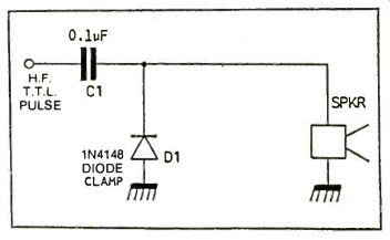
AUDIBLE INDICATOR FOR HF PULSES
When experimenting with high frequency pulses just outside the audio frequency band, e.g. 20k Hz to 50kHz used commonly for ultrasonic range finding and motion detectors, a simple verification is often needed for the presence of such pulses. An oscilloscope is a nice luxury, however failing to come up with the funds, a much easier option is available.
The circuit albeit simple, provides an audibly output in the presence of HF pulses. Alternatives such as an LED indicator cannot differentiate between HF pulses and a latched high state and using just a loudspeaker will not give an indication outside the audio frequency band. This circuit works on the basis that the capacitor blocks any latched high signals and passes pulses only. The clamp diode provides a signal capable of activating the piezo buzzer.
PARTS LIST FOR AUDIBLE INDICATOR FOR HF PULSES
C1-.01uF Capacitor
D1-1N4148 silicon signal diode (or Equiv.)
SPKR-Miniature Piezo buzzer or audible warning device
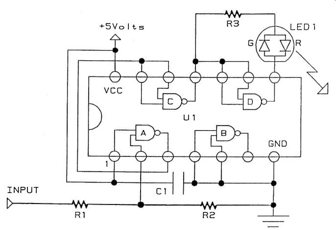
A SIMPLE LOGIC PROBE
Here is a quick and simple logic probe that works great with low speed digital signals. It can be built with a few simple parts: one chip, a bi-polar (two element) LED, a capacitor and a few resistors. The schematic shows a quad two input Nand gate chip but any HC or HCT chip that contains several inverters or inverting gates will work fine. (HCT chips are HOMOS chips that have inputs compatible with TTL logic levels. Using an HCT chip will allow this probe to work with most types of TTL and CMOS logic.) The circuit is pretty simple. Gate "A" of U1 senses and buffers the signal under test. The input resistors, R1 and R2, limit the input current and pull it down so it is stable when not in use. Gates "C" and "D" of U1 provide the current to drive the bi-polar LED. One "sources" the current while the other "sinks" the current depending on the logic level of the input. The 220 Ohm resistor, R3, limits the LED current to about 23 milli-Amps so the gates and the LED do not burn up.
(For you techno-buffs, this method of driving a load is similar to the idea behind "H-Bridge" motor drivers but on a smaller scale.) The capacitor in the circuit, Q1, helps supply the switching currents for the CMOS gates and helps suppress noise.
The logic indication goes as follows: When a "High" is applied to the input, the LED is red, When a "Low" is applied to the input, the LED is green. When a slowly changing signal is applied to the input, the LED will alternate red and green. When a signal above 50 Hertz is applied to the input, the LED will flash red and green very quickly and the color will appear to be some shade of yellow. The particular shade of yellow will depend on the duty cycle of the input signal. Mostly high or mostly low signals will show a slightly discolored red or green, respectively.
As shown in the schematic this probe is intended to be used with logic on a +5V supply only. The input will draw very little current from the circuit under test, but the appropriate logic levels must be maintained to ensure proper operation. The LED is similar to the XC-5491 available from your local Radio Shack store as part #276-012. This circuit could also be constructed with one of the three leaded two element LEDs or even two separate LEDs by tying one of the anodes to the output of Gate "C", the other anode to the output of gate "D" and the common cathode through the 220 Ohm resistor to ground.
PARTS LIST FOR SIMPLE LOGIC PROBE
C1-1 of to 10 uf
LED1-DualColor or Bi-Polar
LED similar to Radio Shack part #276-012
R1-1000 Ohms
R2-22,000 Ohms
R3-220 Ohms
U1-74HC00 or 74HCT00 (see text)
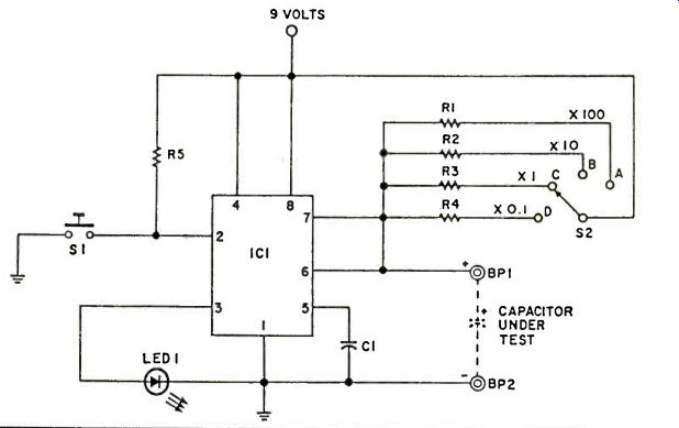
CAPACITOR TESTER
Here is a simple little device that can be used in conjunction with a watch or clock, capable of measurements in seconds, that will measure the value of any electrolytic or tantalum capacitor.
With the capacitor to be tested connected to the binding posts (watch polarities), press and release S1; then time how long LED1 remains on. Multiply the time by the appropriate scale factor and divide by 1.1.
You now have the capacitance in microfarads. For example, suppose S2 is in position B and LED1 has remained on for 11 seconds. The capacitance is then equal to:
11 seconds x 10 (scale factor) = 100uF 1.1
When testing an unknown capacitor, always start at position A. If the time interval LED1 stays on is too short to be accurately measured on your watch, move S2 to the next position. Every time you move S2 to a lower position, you increase the time interval the LED1 will remain on by a factor of ten.
The circuit theory is quite simple. The 555 timer IC is set up as a one shot. When S1 is depressed, the timing cycle is started and LED1 is turned on until the timing cycle is completed.
PARTS LIST FOR CAPACITOR TESTER
BP1, BP2--Binding Posts
C1-.01uF Capacitor
IC1-LM555 Timer
LED1-Light Emitting Diode
R1, R6-10,000-ohm, 1/4 Watt, 5% Resistors
R2-100,000-ohm, 1/4 Watt, 5% Resistor
R3-1,000,000-ohm, 1/4 Watt, 5% Resistor
R4-10,000,000-ohm, 1/4 Watt, 5% Resistor
R5-1,000-ohm, 1/4 Watt, 5% Resistor
S1-Normally open mini SPST momentary switch.
(Radio Shack #275-1547 or Equiv.)
S2-Single Pole 12 position rotary switch. (Radio Shack #274-1385 or Equiv.)
Also see: New Book Reviews
adapted from: Electronics Handbook 1992