By Steve Sokolowski
Throughout the centuries, man has been fascinated by magnetic fields. When discovered some thousand or so years ago, that the earth was encapsulated by this same phenomenon, scientists of that day unearthed a startling fact. By having a small piece of magnetized steel suspended in the air by twine, the needle always pointed to the north. The uncovering of such a strange occurrence eventually led to the highly accurate navigational equipment used today.
Not until four years ago, the ancient compass was catapulted into twenty-first century technology. By combining the miniaturization of mechanical as well as integrated circuitry; techniques, not available until recently; the Dinsmore Instrument Company of Flint, MI, was able to perfect the electronic compass.
With this article, we will introduce you to the Dinsmore Digital Compass. And hopefully spark some interest in the development of some other high tech compass projects of your own.
The Compass Sensor
If one could look inside the compass sensor, he would see something similar to the illustration in Figure 1. Here, a small magnet is allowed to pivot freely around for "Hall-Effect" switches. When pointed north, the miniature magnet turns slowly to align itself in parallel with the earth's magnetic field (or field of flux). When aligned, the attraction supplied by the bar magnet closes the #1 "Hall-Effect" type switch, thus giving a logic "0" at its associated output pin (pin 3), while the others remain at logic "1." If the compass sensor was pointed to the south, the same occurrence would take place, but this time, the #3 "Hall-Effect" switch would close. This closure would deliver a "0" at the pin 3 output of sensor #3 while all others would remain high ("1"). This scenario is just great if there were only four compass directions or headings. But there are eight.
So, what happens if the sensor's bar magnet is pointing between sensor #1 and 4? If this is the case the output pin on BOTH the #3 and #4 sensor will deliver a logic "O." For example, say, you were facing North West. If LEDs were connected to all four output pins, the North and the West LEDs would light.
Indicating Northwest. If you were to make a 180 degree turn, the compass sensor would light both the East and South LEDs indicating a heading of Southeast.
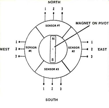
FIG. 1
To show the relationship between all eight compass headings and output data, take a look at table 1. This listing shows which output pin will deliver a logic "0" for each compass heading.
For example, say that the compass sensor is facing North. The Hall-effect Sensor #3 will deliver a ground (or logic 0) to pin #3 of the device. If the anode lead of an LED were connected to this pin, while the cathode had a positive 5 volts on it. The LED will light.
Indicating a heading of NORTH. The same would hold true if the compass was facing West. But this time, the Hall-effect Sensor #4 will place a ground on the anode of another LED, while the output of Sensor #1 will go high. So, if a number of LEDs were placed in an 8 point circle pattern, we can easily indicate the standard compass headings just by lighting the appropriate LED.
How It Works
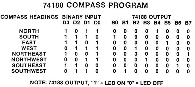
TABLE 2
Figures 2 and 3 show the schematic diagram for our Electronic Compass. As you can see, the compass sensor requires only a handful of inexpensive components. But to make the compass display all eight headings rather than having a dual output, we have included an integrated circuit to the final design.
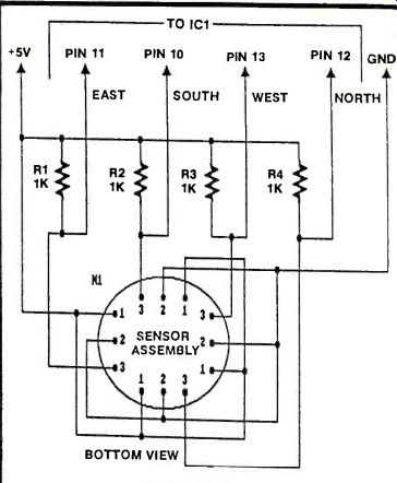
FIGURE 2
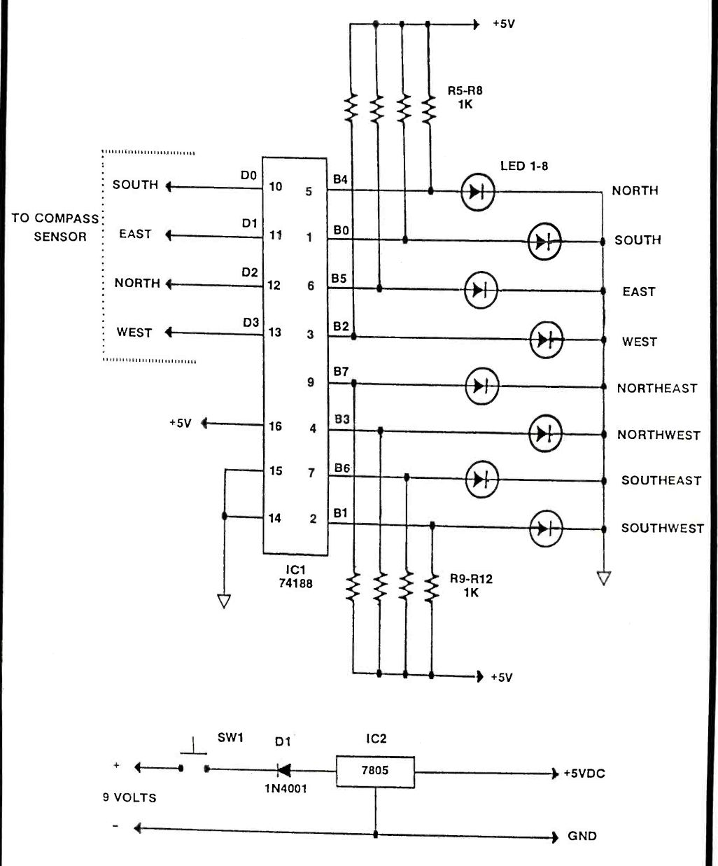
FIGURE 3
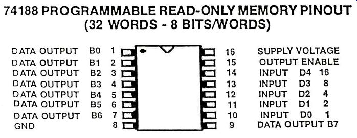
FIG. 4 ----- 74188 PROGRAMMABLE READ-ONLY MEMORY PINOUT (32 WORDS-8 BITS/WORDS)
The 74188 (IC1) is a Programmable "Read Only" Memory (32 words 8 bit /word See Figure 4). When programmed, the chip can easily create a situation that will eliminate the lighting of two LEDs to indicate intermediate compass headings such as north east, south west, etc. The #74188 senses the dual input from the Dinsmore compass sensor then lights the one, and only one, LED that corresponds with this data.
Table 2 shows the internal programming of the #74188. The Binary output from the Dinsmore sensor is weighted 1,2,4,8. Here, we will indicate this as DO, D1, D2 and D3 respectively. The sensor data output then wired to pins 10 to 13 (pin 14 is tied to a logic "1" level) of the #74188 ROM chip. The output terminals (BO to B7) are programmed in such a way as to place a logic 1 at the output pin that will light the appropriate LED. When connected to an LED whose cathode leg is wired to ground, a difference of potential between the two terminals is present. This voltage difference will light the appropriate LED.
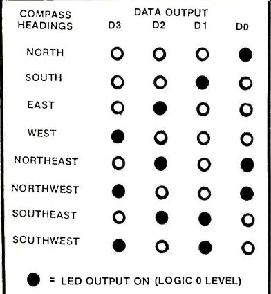
TABLE 1
Seeing that the #74188 is a device that makes use of an open collector output, eight loading resistors in the range of 1K ohm must be connected to each output leg. The other side of the resistors are shorted together and brought to the +5 volt supply.
The Electronic Compass was meant to be a hand held device. So incorporating a 9 volt battery as the power supply is a must for its operation. But, by applying 9 volts to an IC that was manufactured to withstand only 5 volts would be a foolhardy proposition. So to knock the input voltage down to the needed 5 volt level, we have used a #7805 voltage regulator (IC2 TO-220). This IC not only limits the output to 5 volts but it also provides a constant voltage to the circuit even if the battery used had another life in a portable radio.
The only drawback to this circuit is the massive current requirements to light LEDs and to power the #74188, which require about 90 mA for normal operation. For this reason, the Electronic Compass was not meant to be in constant operation. For momentary operation, SW1 was added. Here the spring return button is pushed only when compass headings are required. Then released to conserve battery life which, by the way, should be an alkaline.
Programming the #74188 PROM
The programming of the #74188 requires you to assemble the circuit presented in Figure 5. Here the simulated data output from the compass sensor is delivered to the #74188's input pins (10 to 13) through four single pole double throw switches. The output, requiring a logic 1 output can be selected by using a 1 pole 8 position rotary switch (1 pole 10 position will also be satisfactory). When purchased, the virgin #74188's BO to B7 outputs are all at logic 0 levels. To program a logic 1 at any one of 256 memory locations, an internal "fuse" must be blown. By applying power that is well over the normal operating voltage, internal fuses can easily be opened. Here, in Figure this "over voltage" is 12V. So that you don't destroy adjacent fuses from high current, a 330 ohm resistor is placed in series with the arm of the rotary switch. To allow the insertion and removal of the programmed IC, a 16 pin IC socket should be used.
The power required by the programmer is quite unique, but not impossible to find. Surplus mail order houses sell inexpensive DC power supplies that deliver ±5VDC as well as ±12VDC with a current of about 50 mA. When wiring the circuit, just verify the polarity and level of each output with a volt meter. Then connect the appropriate voltages in place.
Once your programmer in complete, check the wiring and inspect for solder bridges. When all connections have been "inspected" for problems, the time has come to program the logic data onto the non-volatile memory of the #74188.
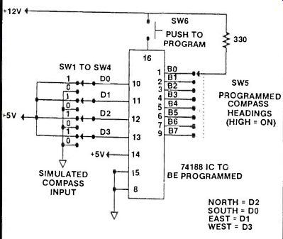
FIG. 5
Step-By-Step Programming of the #74188 To start, place a fresh #74188 chip into the 16 pin IC socket, observing the proper orientation of the chip.
Then turn on the power. Using the data input switches (SW1 to SW4), apply the following binary code:
D3 D2 D1 D
1 1 1 0
This code will simulate the compass' NORTH output.
With the appropriate data applied, turn the SW5 to its B4 position. Then press SW6 (Program Switch) for an instant. Don't hold SW6 down longer than 2 seconds.
This will destroy the IC. When programmed, place DO switch back to its logic 1 position.
Next, let's program SOUTH output by flipping the D1 switch to logic O. SW5 should be in position BO. Press SW6 to program a 1 at this point. Return SW2 to logic 1.
EAST can be programmed by flipping the D2 switch to logic O. SW5 should be at position B5. Press SW6 to program. Return the data switch to logic 1.
Programming WEST can be accomplished by flipping the D3 switch to logic O. SW6 in position B2.
To program, press SW6. Return D3 to its logic 1 position.
NORTH EAST is programmed by flipping both DO and D2 to logic O. SW5 is in its B7 position. Press SW6 to program. Return data switches to logic 1.
NORTH WEST can be programmed by flipping both DO and D3 to logic O. SW5 should be in position B3. Again, press SW6 to program.
SOUTH EAST is programmed by setting D1 and D2 to logic O. SW5 should be set to its B6 position. Press SW6 to program.
Final SOUTH WEST can be programmed by applying a logic 0 level to both D1 and D3. SW5 is placed in its B1 position. Press SW6 to program.
This completes the programming of the #74188.
But there is an easier way to get the same results.
How? Consider purchasing a pre-programmed PROM from Suncoast Technologies, Spring Hill, Florida. Why not let them do the work, why should you?
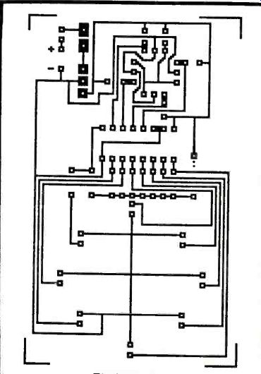
FIGURE 6
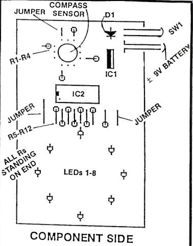
FIGURE 7--COMPONENT SIDE
Construction
The wiring of the Electronic Compass is relatively simple. But the compass does require the use of many polarity sensitive components. Such as the LEDs, ICs and most of all, the compass sensor itself. To help minimize the burnout of the fragile components, Figure 6 shows the 1:1 artwork for the circuit board, while Figure 7 illustrates the component layout. If you follow the layout diagram, you should have no problem in the construction of the circuit. Just remember to double check all component orientation before soldering. All orientation is shown on Figure 6.
Care must be taken when installing the LEDs in their appropriate holes. All LEDs have their cathode leg connected to ground. Note that the placement of the LED indicating North is in reverse to all others (See Figure 8). Also note that the PC Board requires three jumper wires that must be installed.
With all the LEDs and resistors installed on the board, the last components to be soldered are the compass sensor, IC1, and IC if you wish, IC1 can be installed on a 16 pin DIP socket. By using a socket, destructive heat generated by the soldering iron can be eliminated altogether, without worrying about "blowing" the device. While soldering the compass sensor and voltage regulator, a heatsinking material should be clipped on their leads before applying heat.
A simple alligator clip can be used as such a device.
But be careful when removing it since it will be hot to the touch. If care is not taken, severe skin burns can occur.
we've included copper traces on the PC Board where they can be soldered. These locations will provide a strong connection point for the series circuit as well as enhancing the appearance of the overall project.

FIGURE 8
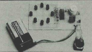
The final wiring of the compass takes the form of the 9V battery clip and the push button. These parts can be wired in any number of ways, but for clarity, When properly assembled, the Electronic Compass draws about 100mA of current for its operation.
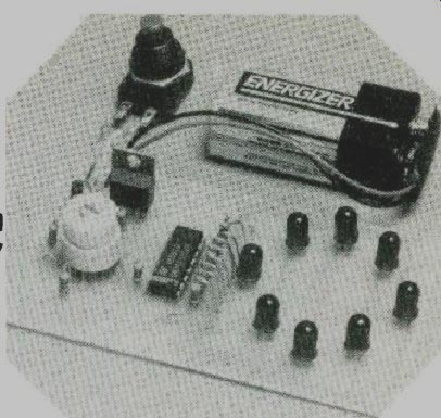
Standard carbon 9v batteries can deliver this amount current but for only a brief period. To overcome this problem, it is recommended that the Electronic Compass be powered by high quality alkaline or lithium batteries. While higher in price, these premium batteries will be able to handle the current requirements of the project. Eveready, Kodak (See Figure 1A and the "copper top" (Duracell), to name a few, will power the compass for months without a battery replacement.
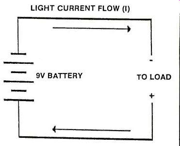
FIGURE 2A
If you're like me, you have a junk box full of inexpensive 9v batteries. So why not use these? Sure you can. But you need to put some basic electronic theory into practice. Figure 2A illustrates how the current of a common battery flows through the copper interconnecting wires to its destination, the load, which represents how much power must be delivered by the battery for the normal operation of the circuit. It is expressed as RESISTANCE. In our case, the LOAD is represented by the Electronic Compass. By making use of the formula:
CURRENT (I) = VOLTAGE (E) / RESISTANCE (R)
you can see that if the load resistance increases, the current being consumed by the circuit decreases. In contrast, if the load resistance decreases, the current requirements increase.
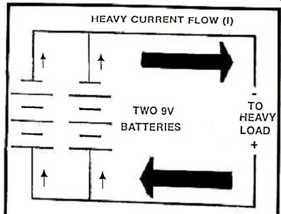
FIGURE 2B
Figure 2B shows a simple series hookup containing a 9v battery and a Load. If the load resistance is in the range of 5000 ohms, the current being drawn will be 1.8mA (or .0018 Amps I =E /R 1=9/5000). With a current this low, a standard carbon composition battery will have no problem driving the load for long periods of time. But on the other hand, with a load resistance of 90 ohms as, in our compass, the current that is needed will be 100mA (or .1A) An extremely large amount of energy for a carbon battery to deliver. But hold on a minute, we can increase the current handling of the battery by wiring two batteries in parallel. This can be seen in Figure 2B. Think back for a moment to those thrilling days of yesteryear (school days). If two batteries are tied together in parallel, the total current is equal to the sum of BOTH sources. Or in other words, Total current is equal to the current from battery one plus the current from battery two. (I_total =I1 +I2). So if we take two 9v battery clips and solder them in parallel as shown in Figure 2B, to the provided holes in the pc board, and snap a couple of transistor radio batteries in place, the current requirements for our Electronic Compass will be easily met without purchasing expensive alkaline substitutes. The total driving current of the two batteries will be significantly increased, thus providing the power needed by the compass circuit.
Cigarette Lighter Adapter Power Option
When completed, the Electronic Compass can be housed in a small PLASTIC box for hand-held use.
Just make sure that you have enough room inside for the batteries. However, the compass is not restricted to tramping through the woods. By adding an inexpensive adapter to the completed circuit, the compass can also have frequent use in either your car or boat. This device is a Cigarette Lighter Plug (See Figure 3A.Since the compass utilizes a 7805 voltage regulator, any DC voltage in the range from 6 to 25 VDC can be used to power the device. Car and boat batteries are of the 12 volt variety, which present no problems. The adapter plug is an inexpensive item that can be purchased at any Radio Shack store or from electronic mail-order suppliers. When your adapter arrives, take a look at Figur4A for a diagram showing the proper wiring. Note that one of the two line cord wires has a white stripe on it. This stripe called a "tracer" is used to indicate the positive ( +) lead. In contrast, NO trace, obviously, is the negative lead (-).
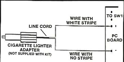
FIGURE 4A
To install the adapter, unsolder and carefully remove the 9v battery clip from the board. Clean out each hole with a desoldering tool or solid piece of wire if solder somehow flowed inside. With our polarity requirements in mind, take the adapter's tracer lead, insert it into the hole requiring positive voltage ( +), and solder it into place. The non-tracer lead is to be installed and soldered to the remaining hole. When complete, "check" the board for any unwanted solder splashes before plugging in the adapter.
Now, sitting in your car or boat, take the adapter plug and insert it into the cigarette lighter. Holding the compass parallel to the ground, press SW and note which LED lights. This indicates the direction the compass is being held.
Another option that you might want to consider if using the cigarette lighter adapter, is the permanent removal of switch SW1, because when the engine of the car or boat is turned off, voltage to the vehicle's cigarette lighter will be cut off, thus removing power from the compass. Just remember to place a jumper wire between the two SW1 PC Board holes.
Testing
When the PC Board is inspected under strong light to ensure that there are no solder splashes or bridges, take a 9 volt alkaline battery and connect it to the provided clip. Facing a known direction, hold the compass in parallel to the ground. Press SW1 and note the lighting of the appropriate LED. Slowly spin around and check for the advancement of the LEDs as they light and extinguish in the proper sequence. If the north LED doesn't light, double check to see if the device was inserted in the proper direction. If no LED lights, check to see if a positive 5 volts is present at pin 16 of IC1. Also check for proper grounding of 101's pin 8. If no voltage is present, check IC1 for proper insertion and finally, check diode D1. It might be open or reversed on the board.
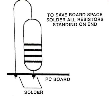
FIGURE 5A--------TO SAVE BOARD SPACE SOLDER ALL RESISTORS STANDING ON END
PC BOARD
SOLDER
Added Assembly Instructions
If you choose to assemble the compass using a home brewed PC Board or by purchasing the complete kit from Suncoast Technologies there are a few things you must be made aware of. All resistors must be installed and soldered while standing on end (See Figure 5 A . By placing components on end, precious PC Board space is saved. And at 500 a square inch, you can appreciate this saving.
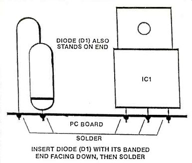
Diode D1 is another component that must be soldered on end. Unlike the resistors, diodes have a polarity and they must be installed in a certain way. If not, the compass just won't work. Figur6A shows the proper installation procedure for D1. Note that the banded end of the diode is facing downward. Also it's installed with the body towards the 7805 voltage regulator (IC1).
FIGURE
6A-----INSERT DIODE (D1) WITH ITS BANDED END FACING DOWN, THEN SOLDER
By taking these simple precautions, the Electronic Compass will provide years of dependable service.
And best of all, you can say, "I built it." If you wish to house your compass, a metal case is definitely a No-No. The earth's magnetic field will be interrupted and erroneous reading will result. The compass housing should be made only of plastic.
Boxes of this type are readily available and inexpensive. And can be found at any Radio Shack store.
Whichever troubleshooting or housing technique you use to get your Electronic Compass at the stage of final assembly, just remember that the use of a printed circuit board in any project will pay for itself in no time and will provide trouble-free operation for years to come.
PARTS LIST FOR THE ELECTRONIC COMPASS
R1 to R12-1K ohms 1/4W Resistor
IC1-Programmed #74188 ROM
IC2-#7805 5V Voltage Regulator (TO-220)
D1-1 N4001 Diode
LED1 to LED8-Standard Red Light emitting diodes
M1-Compass Sensor
MISC.--Plastic Housing, Printed Circuit Board, 9V Battery, Battery Clip
adapted from: Electronics Handbook Vol. X