By Walt Sikonowiz
By Watching Out For Noise, You Can Build a Project That Works Right...The First Time.
Project-Building is supposed to be, and generally is, a challenging and entertaining adventure. Yet, there are times when it can turn out to be a miserable disappointment, all because of a pesky little gremlin known as electronic noise. To the electronic engineer, noise is a catch-all term that refers to any signal appearing someplace where it does not belong.
Even if you have constructed just a few projects, chances are that you have been introduced to noise, whether you realized it or not. While noise cannot be eradicated completely, it can be effectively minimized once you understand its origins. In most instances, the key to a noise-free project lies in good construction practice, so let's examine some of the techniques used by skilled project builders.
When dealing with electrical interference, it is helpful to define two classes of devices; noise sources and noise receivers. Noise originates at some source and appears in another electronic circuit, the receiver.
Almost anything can be a noise source. Some of the more common ones are automobile alternators, arcing motors, the ever-present 60-Hz power line, high-voltage or high-current electronic circuits, and digital logic. Similarly, almost any electronic circuit can be a receiver, although high-gain, low-level, high-impedance stages are often the most susceptible.
While the source and receiver may belong to two different pieces of equipment, they may just as well be different stages of a single piece of equipment.
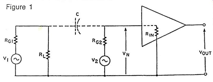
Figure 1. Electric-field coupling between two adjacent circuits can cause
interference problems, particularly if a low-level stage is close to a moderate-level
or high-level stage.
Coupling
In order to transfer energy from the source to the receiver, some form of coupling must exist. The two important modes of coupling consist of an electro-magnetic field or a common ground impedance between the two circuits in question. Consideration of an electromagnetic field is usually broken down into two sub-cases: electric-field coupling and magnetic-field coupling. A high-voltage, low-current circuit radiates energy chiefly through an electric field, whereas high-current, low-voltage circuitry radiates predominantly through a magnetic field.
Most noise sources radiate through both fields, but it is easier to deal with one field at a time.
Let's begin with electric-field coupling, also known as capacitive coupling. In Figure 1 we have voltage source V,, with internal impedance RG1, driving a load, This voltage generator might anything-a transistor, op-amp, logic gate, or even an alternator; the exact nature of the source is unimportant. Nearby, we have a second voltage generator, V2 with an internal impedance of RG2. An amplifier, with input impedance equal to R N, is supposed to amplify V2.
However, electric field coupling between the two circuits exists through stray capacitance C. Now, C's capacitance will be very small. As an example, consider that the capacitance between two closely spaced #22 wires amounts to less than 40-pF per foot of wire. Despite the small magnitude of capacitance C, however, it can result in the appearance of a noise voltage, VN, across the amp's input impedance. We are in trouble if VN is a significant fraction of V2's magnitude, and the situation is hopeless if VN equals or exceeds V2.
To see what determines the size of noise voltage VN, note that current from generator V, can flow in a complete loop: first through Roi, then through C, and finally through RG2 and RIN back to source V,. Since RG2 is effectively in parallel with RIN, and since VN is developed across this parallel resistance combination, we are interested in the equivalent parallel resistance, which we abbreviate as RG2 // RIN. Basically, what we have here is a voltage divider-Roi , C, and RG2 // RAN-across V,. The noise voltage caused by V, will be increased by the following factors: 1) an increase in the magnitude of V,; 2) an increase in the frequency of V,, since C's impedance drops at higher frequencies; 3) a decrease in source-to-receiver distance, because this increases C; and 4) an increase in the equivalent parallel resistance, RG2//RN. Voltage and Frequency It is apparent that high-voltage, high-frequency circuits are the most trouble-some noise sources, as far as the electric field is concerned. Digital logic is one of the most common examples of this type of circuitry. Signal swings are large--between five and fifteen volts usually. Furthermore, even though the repetition rate of the pulses or square waves involved may be low, these signals still have a high harmonic content. For example, pulses with a 5-nano-second rise-time have significant harmonic energy right up to 30 MHz., even if the repetition rate is much less than that.
At the receiving end, the most noise-susceptible circuits will have high impedances and operate at low levels (that is, with small V2). This latter factor, low levels, is very often accompanied by high gain.
Common examples of such noise-sensitive circuits are: high-gain FET preamps, low-level analog comparators, and op-amps with large feedback resistors.
Assuming that you cannot change the design of the source and receiver circuits, the only practical method of reducing noise from an electric field is to minimize the coupling capacitance. Separation of the two stages helps; at least an inch or two should intervene between the circuits. Separation beyond this distance will reduce pickup still more, but the noise level does not drop as quickly as it does over the first inch or so.
Shielding
More effective than separation is the use of a metallic shield when pickup is severe. In Figure 2, the two possible methods for shielding are diagrammed.
Figure 2A shows a conductive metal shield, grounded to source common, that completely encloses source V,. Electric-field coupling between source Vi and the shield is symbolized by capacitor C,. Outside the shield, another stray capacitance, C2, exists between the shield and the equivalent parallel resistance, RG2 / /RN. (The rest of the amplifier has been deleted because, so far as we are concerned here, its only important characteristic is RAN.) An electric field exists within the shielded enclosure; however, the field outside the shield is zero everywhere. This comes about because, at least ideally, the entire surface of the shield remains at ground potential. Since the external field is zero, no energy is transferred across stray capacitance C2.
In part B of Figure 2, the grounded metallic shield envelops the receiver. Energy transfer occurs between source Vi and the grounded shield via C1.
The field within the shield is zero since the shield is at ground potential. As a result, no noise is picked up by the receiver.
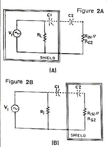
Figure 2. A grounded shield is very effective against capacitive coupling.
The shield may be applied either around the noise source (A) or around the
circuitry where noise is being picked up (B). Aluminum is a good shield metal
as are copper and steel.
Any metallic sheet makes a good electric shield. Aluminum, a common cabinet material, is excellent at all frequencies. A shield may be placed between two stages of a single piece of equipment. On the other hand, a grounded metallic cabinet constitutes a shield between a particular piece of equipment and all noise sources in the outside world. The only precaution necessary when shielding is that the shield must be in electrical contact with the circuit's ground. Note that this does not necessarily mean an earth ground, such as a pipe in the soil. Connection to circuit common is all that is ever required.
At this point, you are probably wondering what happens if the source and receiver circuits do not share a common ground connection. We can treat this coupling by means of two stray capacitances, as shown in Figure 3. You should be able to see for yourself that the previously discussed shielding methods still apply. A shield around either circuit, connected to that circuit's ground potential, is all that is required.
Before leaving the electric-field case, let's note that wires may also need shielding if they connect to possible receivers or sources. When wires exit a particular piece of equipment, they may be protected by shielded cable. Likewise, shielded cable may be used within a single piece of equipment when interstage noise coupling is a problem. Often, however, you can obtain the benefits of a partial shield by simply routing wires close to the grounded chassis. The electric field near the chassis /shield is minimal, so any pickup by wires is likely to be small. As a final precaution, keep wiring to low-level circuitry separated from high-level wiring.
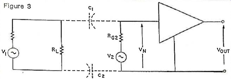
Figure 3. If there is no common ground connection between the noise source
and the receiver, electric-field coupling may be represented by two
stray capacitances--C1 and C2.
Inductance.
Now, let's turn to the magnetic field and Figure 4.
The most important aspect of this is that there are two current loops, a source loop and a receiver loop. In the source loop, generator V1 drives a current through load RL. The current flow is, in turn, responsible for a magnetic field that exists in the vicinity of the source loop.
The receiver loop consists of generator V2 driving a stage with input impedance RN. (Note that no internal resistances are indicated for the voltage generators since such impedances have a negligible effect here.) In addition, a noise voltage, VN, which is due to source Vi, appears in series with V2. If VN is not negligible compared with V2, then we must find ways of minimizing the noise pickup.
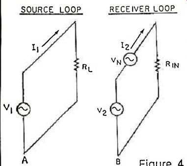
Figure 4. Magnetic field or inductive coupling requires the existence of
two complete current loops. Shielding against a magnetic field is difficult
in home construction.
What we have in Figure 4 is a simple transformer, which suggests why magnetic coupling is also known as inductive coupling. Alternating current I, generates a changing magnetic field that induces a voltage in any loop it intersects. As Figure 4 shows, the two current loops may be completely isolated.
However, points A and B could be connected with no change in the induced noise voltage. Therefore, as was the case with the electric field, we must consider coupling between stages of the same device, or between stages of two separate devices.
Let's examine the factors that cause increased noise coupling: 1) an increase in the magnitude of 11; 2) a decrease in the separation of the two loops; 3) an increase in the frequency of 11; 4) orienting the loops so that their planes are parallel; and 5) an increase in the area of the receiver loop. From the above, several methods of noise reduction are suggested. First, separate the two loops; in particular, keep high-current stages away from low-level stages. Second, minimize receiver loop area. This applies especially to the wiring associated with a receiver stage. All wires to a jack, a switch. or a potentiometer should be twisted together, thus minimizing pick-up loop area.
Third, try to minimize the source loop's magnetic field. This is most conveniently done by using twisted wires again. To see why this is effective, imagine taking the source loop, stretching it, then twisting the wires together. The currents in the twisted pair flow in opposite directions, and because twisting keeps the two wires in close proximity, the magnetic field of one wire cancels that of the other. Even better than a twisted pair, especially at high frequencies, is coaxial cable; for most hobbyist requirements, however, a twisted pair is sufficient to reduce magnetic radiation.
Finally, changing the orientation of the source with respect to the receiver often helps. Consider, for example, the magnetic radiation from a power transformer. You may carefully twist the leads but you cannot do anything about the magnetic flux from the transformer coils. Usually, however, some mounting orientation of the transformer will result in minimized pickup in your noise-sensitive stage.
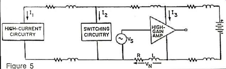
-----------Figure 5. Ground noise can originate in any system where power
is distributed in a serial manner. Resistance and inductance on the power
lines can create unwanted ground noise.
Comparing magnetic coupling with electric coupling, one thing you may have noticed is that the impedance of the receiver has no effect on its susceptibility to inductive coupling. Also, you may have wondered whether a shield would be as effective against a magnetic field as it is against an electric field. The answer is no. Aluminum, which is so effective as an electric shield, begins to be effective against magnetic fields only at higher frequencies (above 100 kHz). At the important frequency of 60 Hz, aluminum is useless. In order to obtain better magnetic shielding, your shield must be a ferromagnetic substance, such as steel. Because it is harder to machine than aluminum, steel is rarely used by hobbyists, even though its magnetic-shielding properties are superior to those of aluminum. At 60 Hz, however, even steel is only partially effective (shielding effectiveness increases with frequency). Special magnetic alloys, such as Mu-Metal, are necessary at low frequencies. All things considered, magnetic shielding is more difficult than electric shielding.
Wiring Problems.
So far we've dealt with stray pickup from a more or less familiar viewpoint-familiar at least in the sense that whenever noise problems occur, the first thing to be blamed is some mysterious, invisible field. Very often, however, the trouble is the handiwork of a more mundane villain: your circuit's electrical wiring.
Figure 5 shows a serial power distribution system, the most common way of delivering power to the various stages of a piece of equipment. Two power leads run from the supply to one stage, and then from there to the next stage, and so on. Such a scheme is simple and generally practical, except when you have the situation shown in Figure 5. Here we have a low-level source, Vs, driving a high-gain amp stage, with resistor R and inductor L representing the resistance and inductance of the interconnecting ground lead.
Current I1 from the high-current stage and current I2 from the switching stage both flow through the power bus-in particular, through R and L. Since the amp responds to the potential difference between its input and ground leads, any voltage developed across R and L due to I1 and I2 appears in series with Vs, and this noise voltage VN gets amplified right along with VS.
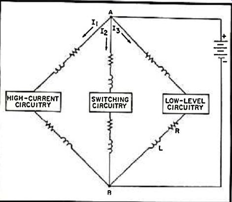
Figure 6. When different types of circuits are sharing a single power source
in a parallel distribution system, ground noise is often totally eliminated.
The arrangement isolates the various circuit components from their neighbor's
power source. The power source should have low impedance and be connected
to points A and B by very short wires.
Now let's suppose R and L represent a piece of #22 wire. One foot of #22 has a resistance of 16.14 milli-ohms, and if I1 is a direct current of about 61 milliamps, then VN equals 1 millivolt. This is small, but certainly significant if VS is also on the order of millivolts. At high frequencies, the impedance of inductance L increases to become the dominant factor, and this gives us even more trouble. For example, a foot of #22 wire has 4-ohm impedance at 1 MHz, and a whopping 40 ohms at 10 MHz. Needless to say, high-current and high-frequency stages (and this includes our old friend, digital logic) can wreak havoc on low-level circuits.
What can be done? First, current spikes from digital logic may be reduced by bypassing ICs with 1-mfd. ceramic capacitors. These capacitors are applied as closely as possible to the power pins of the various IC packages. Another scheme that is successful at frequencies below 1 MHz is the use of a parallel power distribution system, as shown in Figure 6. Since I1 and I2 cannot flow in R or L, they produce no troublesome noise. In order for this system to work well, however, the power supply must have a low impedance and use very short wires.
Summary
The key to minimizing noise transmitted through an electromagnetic field lies in separation of the noise source and receiver. Keep high-voltage and high-current circuitry away from stages that carry low-level signals. Be especially wary of digital logic, one of the worst offenders where noise is concerned because of the magnitude and switching speed of the signals involved.
When separation has been carried to its practical extreme and noise pickup is still a problem, put a grounded metallic shield around the noise source or receiver. If signals are being radiated or picked up by wires, use shielded coaxial cable. Sometimes the shield is allowed to carry current, in which case it is grounded at both ends. At other times, we may prefer that the shield carry no current, and it will be grounded at one end or the other, but not both. The question of whether to ground the shield at one end or two is beyond the scope of this article. Since most of you will be building projects from plans rather than designing your own circuitry, the best advice here is that you use the kind of shielded cable specified by the project's designer and wire it exactly as he did.
To avoid the often disastrous noise problems that may arise when incompatible currents flow through a common ground impedance, use a printed-circuit board if one is available. You can either buy a ready-made board or etch your own at home provided the plans are available. If for some reason you prefer to use perfboard or wire-wrapping techniques to build a project, do yourself a favor and copy as closely as possible the layout and wiring of the project's PCB. Now, it is true that there are a great many circuits that will never cause any trouble no matter how carelessly they are wired. Unless you know for certain, however, that a project is failsafe, it pays to be smart and copy the designer's original layout. Then, if something should go wrong with the project, at least you'll know that the layout is not to blame. The less you tempt fate, the better your chances are of building a project that works.
adapted from: Electronics Handbook Vol. X