
By William R. Hoffman
From its introduction almost two decades ago, the simple, lowly operational amplifier (op-amp) has probably become the most used functional analog circuit "block" in semiconductor history. From that first IC circuit, called the 709, has come all of today’s analog semiconductor circuits, from high performance low noise preamplifiers to large, high power amplifier stages. The basic circuit, usually composed of a differential input stage followed by one or more voltage gain stages, and ending with a push-pull output circuit configuration, can be made to do almost anything from analog amplifiers and filters to digital comparator functions. And because of the universal availability and low cost, as well as simplicity of designing with them, even the home experimenter can successfully create a large variety of circuit functions with only a pencil and paper and pocket calculator.
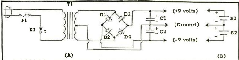
Fig. 1. (A) is AC operated power supply for op-amp circuits.
F1 is a 0.5 A fuse. T1 is a small 120V to 12V power transformer rated
at 100 mA or more with a center tapped secondary. D1 to D4 are small
silicon diodes rated at 1 A with at least 50V PIV. C1 and C2 are 470
uF 16V capacitors. For the battery supply (B), simply connect two 9V
carbon-zinc transistor radio batteries as shown.
SOME BASIC INFORMATION
To begin with, lets look at some of the op-amp's characteristics, so we can learn some basic things about them, necessary for us to do our own design work.
Their inputs (there are two, one marked + or non-inverting, and the other marked-or inverting) is where we apply the signal or reference input into the IC. If we choose the non-inverting input, then the output will have the same phase as the input.
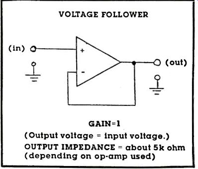
--------(in) a VOLTAGE FOLLOWER (out) .... GAIN =1 (Output voltage =
input voltage.) OUTPUT IMPEDANCE = about 5k ohm (depending on op-amp used)
However, if we go into the inverting input, then our output will be an inversion of the input signal. Both can be used, and each has a specific application. Note that the input impedance for the non-inverting input is very high; very little current is used from the source signal to produce an output. On the other hand, the inverting input, because it is where the feedback is applied from the op-amp's output, has an impedance near zero ohms. Therefore, an input resistor must always be used to protect the source of the input signal. The only other rule to remember is that the input voltage must NEVER exceed the supply voltages going to the op-amp from the power supply, not even for a fraction of a second or the circuit will be damaged and the IC will fail completely.
The op-amp has only one output where, as indicated above, the signal may be either an inverted or non-inverted copy of the input. Depending on the feedback resistance, the op-amp can also have considerable gain; the input signal can be amplified up to many thousands of times, and the output impedance is usually low enough that the circuit can put out many milliamperes of current with voltage swinging from just a little less than the positive supply voltage to just a little less than the negative supply (typically +/-12V. from a +/- 15V. supply).
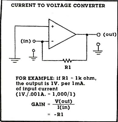
------ CURRENT TO VOLTAGE CONVERTER
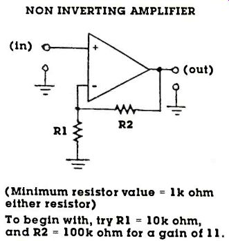
------ NON INVERTING AMPLIFIER
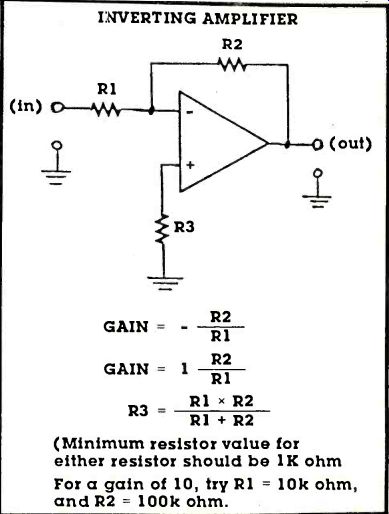
------ INVERTING AMPLIFIER
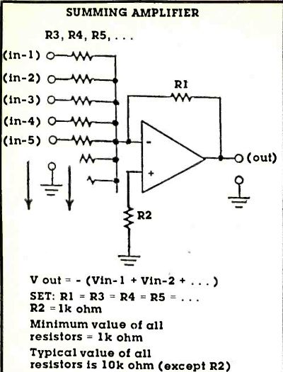
--- SUMMING AMPLIFIER---NOTE: input impedance of all inputs is equal
to input resistor value (R3, R4, etc.)
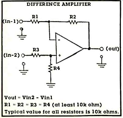
--- DIFFERENCE AMPLIFIER
Finally, we need to know about the power supply for the circuit. Most op-amps can run on supply voltages from +/- 4V. to +/-15V. with little change of circuit performance. And with their high efficiency design, they typically consume only a few milli-amperes of current making a small, unregulated AC supply or even two batteries a very practical way of powering them. For the circuits described here, if we wish to use them continuously, a power supply circuit consisting of a transformer, some rectifiers, and some filter capacitors is shown in Fig. 1. Most of the parts necessary can be found in a well stocked experimenter's junk box. If not, they are readily available from most any electronics parts supplier. You should be able to build the power supply for under $15.00, even from brand new parts. If you build it, just be careful with the input wiring: 120V AC can be a shock hazard. Also, when wiring the rectifiers and filter capacitors, be sure you get the polarities correct! The entire circuit can be built on or in a small sheet metal box, with the wiring on a couple of terminal strips.
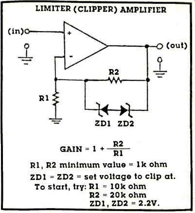
----- LIMITER (CLIPPER) AMPLIFIER
HELPFUL REMINDERS
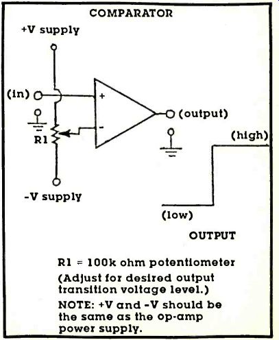
----- COMPARATOR
Some hints. Like all good circuit layouts, be sure and keep the input and output away from each other.
This will help prevent oscillation. Also, if you will be running more than a foot or so of wire from the power supply to the op-amp, be sure and add some 0.1 uf. 50V. capacitors from each of the power supply lines to ground. Do this near the op-amp power supply pins, to help prevent any possibilities of oscillation. With this in mind, let's start looking at some of the op-amp circuits.
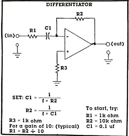
-------- DIFFERENTIATOR
LOTS OF CIRCUITS
On the following pages are 18 op-amp circuits complete with design equations and some suggested circuit component values to help you get started.
Note that none of the diagrams show any pin numbers or power supply connections since these may change from IC to IC. Consult the data sheets which come with the IC's you purchase to determine their locations and operating values.
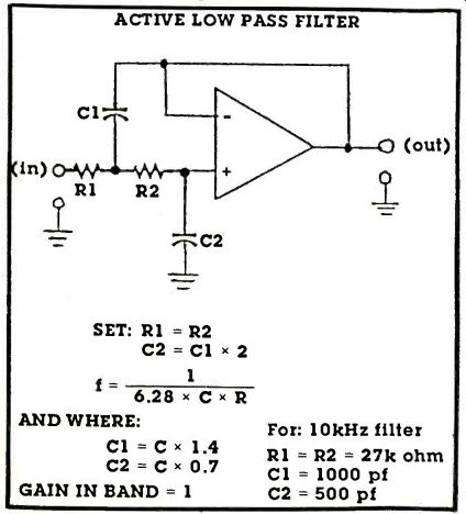
------ ACTIVE LOW PASS FILTER
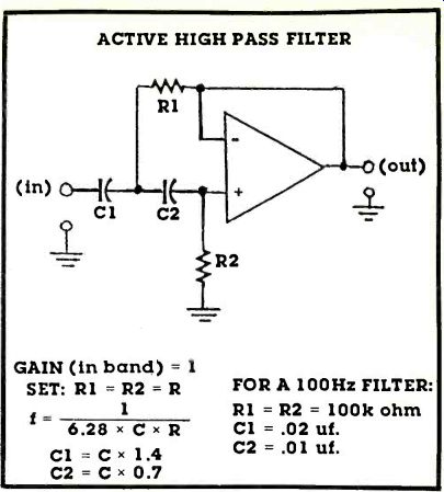
------ ACTIVE HIGH PASS FILTER
AMPLIFIER CIRCUITS
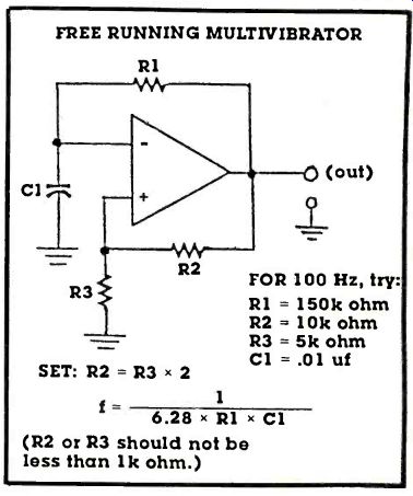
------ FREE RUNNING MULTIVIBRATOR
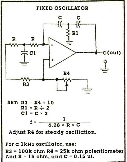
------ FIXED OSCILLATOR
We have a choice of amplifier types. Linear INVERTING or NON-INVERTING are the basic amplifiers we are mostly familiar with. They can amplify weak signals from a pickup cartridge or microphone for use with a stereo, or the weak signals from a light sensor to detect when a beam is interrupted; the uses are almost endless. The only difference between the two is just what their names imply: one inverts the signal at its output, the other doesn't. The VOLTAGE FOLLOWER is a simple variant on the amplifier stage: it has no gain, but serves to isolate the input signal from whatever is connected as a load. The current gain of the amplifier (it has no voltage gain) will allow a very high, high impedance source (like a transducer of some kind) to drive a low impedance load (like a meter or a lamp).
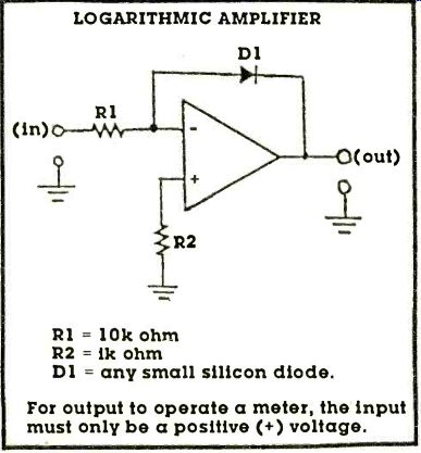
-------- LOGARITHMIC AMPLIFIER
The SUMMING AMPLIFIER and DIFFERENCE AMPLIFIER are both linear like all the others, in addition they allow us to add two or more signals together and get an algebraic sum or difference at any given moment-these actually perform an arithmetic function for us! The METER AMPLIFIER is just what its name says, an amplifier just to drive a meter so that we can measure the level of a signal or compare two signals. This can be used with the summing and difference amplifiers for special functions, such as reading the simultaneous output of two stereo channels, or with the difference circuit, read the separation of the signal-a very versatile combination. The LIMITING AMPLIFIER also does what the name implies-limits or clips our signal if it exceeds the circuits set limit. And finally, the LOG AMPLIFIER does a very curious thing: it converts the linear input signal to a logarithmic one at the output; it is the simple basis of a compressor or expander circuit (expander as it is shown). As it is, a positive input signal will come out with a positive expansion: it can be used to make a decibel scale reading meter along with the meter amplifier above.
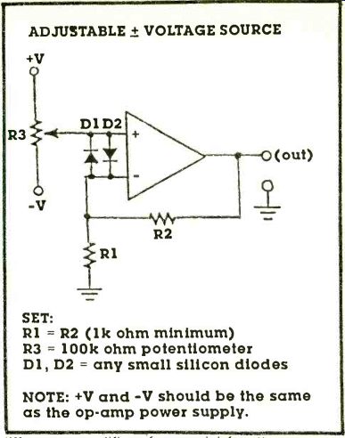
----------ADJUSTABLE +/- VOLTAGE SOURCE
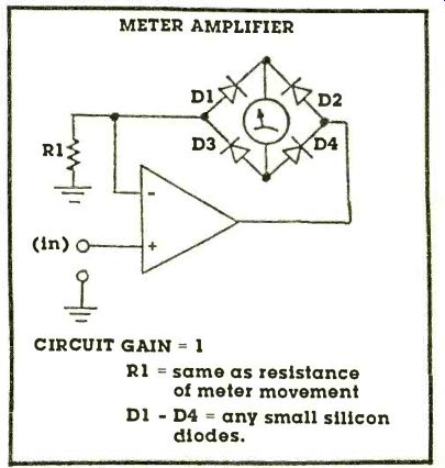
-----------METER AMPLIFIER
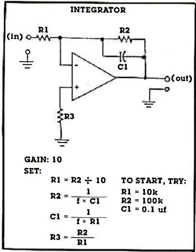
---------INTEGRATOR
ANALOG FILTERS
These are, as the name implies, filters for cutting off or removing parts of the signal frequencies input to them. For example, the HIGH PASS FILTER will eliminate low frequency noise or rumble from a stereo system, while the LOW PASS FILTER may be used to eliminate hiss or other high frequency noises. Both of these filters give a 12 db per octave cutoff response, which is quite fast. Also, by carefully choosing our cutoff values, we can use them with multiple stereo amplifiers to create a hi-fi "biamplified system" with an amplifier each for the tweeters and woofers in our speakers.
WAVEFORM GENERATORS
For those interested in amplifier testing, or checking digital circuit functions, these are two very useful circuits: the FREE RUNNING MULTIVIBRATOR and the FIXED (sinewave) OSCILLATOR. The former generates a continuous train of pulses whose rate is set by the capacitor in the circuit, while the latter will make very good sine waves for testing a high fidelity amplifier for power and distortion.
WAVESHAPERS
Sine or pulse (or music) waveforms can be altered by the DIFFERENTIATOR or INTEGRATOR circuits.
The differentiator will create short, sharp spikes with each input wave to the circuit, while the integrator will take an input waveform and create a sloping, ramped version of it. Both of these circuits are commonly used in making electronic music, or used in creating special musical effects along with the output of an electric guitar or organ.
MISCELLANEOUS CIRCUITS
The CURRENT TO VOLTAGE CONVERTER does just what the name implies; makes a value of input current into a specific value of output voltage. It can operate a buzzer or light when a photo sensor connected to its input detects darkness, or a changing light input. For those needing an ADJUSTABLE VOLTAGE SOURCE this circuit can provide an adjustable output which can be anything from just a little bit less than the positive power supply to a little less than the negative supply voltage. This will make a good reference to operate a power supply regulator circuit, since its output is too low to operate a radio or tape player directly. The PEAK DETECTOR is an especially good circuit for those who need to read power or signal levels since it will momentarily hold a peak value making it much easier to read. This is especially good for those who do tape recording or want to determine the power of their stereo. Finally, the COMPARATOR will act like a digital circuit, changing its output voltage from full negative to full positive when the varying input voltage goes higher than the reference input voltage. As a threshold detector, it can sense when a certain level of darkness is reached when detected by a photocell, or compare two voltages and operate an alarm when something has changed.
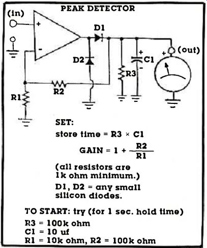
------PEAK DETECTOR
USING THE CIRCUITS
As it has already been suggested, there are many ways to use these circuit function "blocks" especially in combinations. The possibilities are almost endless! Don't be afraid to experiment, a circuit failure, due to an incorrectly installed part or incorrect wiring, should be easily corrected-most won't do any harm to the IC, which in any case is easily replaced if a failure occurs. Good luck
adapted from: Electronics Handbook Vol. X