STABILIZING RF OSCILLATOR DRIFT
The quality of any RF based device (receiver, transmitter or signal generator) can be defined by how stable the frequency of oscillation is. RF oscillators operating in the higher frequency region (ten's of megahertz and upwards) will drift in frequency under some worst case construction/layout conditions. At low frequencies, this drift in frequency might be tolerable, but for reliable long term operation, high frequency-operation drift is a no-no! The popular low power license free FM transmitter design using a single transistor will operate around 100MHz. Even a 1% drift of 1MHz either way is quite considerable. There are several basic 'good' construction layout techniques to follow to minimize and control frequency drift.
1. One of the most critical influences on frequency stability is temperature, particularly high temperatures and temperature variations. Therefore, physically locate the oscillator away from any component that is generating excessive heat, such as regulators and power transistors that consume high current.
2. Use an IC voltage regulator that supplies only the oscillator, so that its supply line is not affected by any of the other circuits components. A circuit block such as a power amplifier feeding into a low impedance load, will cause the supply current, hence supply voltage, to fluctuate as the load current changes. This change, if allowed to 'interfere' with the oscillator, will cause a frequency drift.
3. Keep the frequency controlling components firmly mounted. In the simple FM transmitter design, the frequency associated components are a capacitor and inductor. The capacitor is generally a small trimmer and is not much of a problem. The inductor, generally a small hand wound coil, will cause a change in frequency if the turns are allowed to move relative to each other. Make sure the construction is firm-use epoxy if required to keep turns in place and make sure the coil cannot move especially if the project is a portable device.
4. Insulate the RF oscillator with a 'box' made from a polystyrene sheet. Polystyrene is an excellent heat insulator. The sheets can be cut easily to shape with a hobby knife and glued together with contact cement. The heat shielding properties with a 'poly' cover are quite considerable.
-----------------
JACK SOCKET TUTORIAL
Miniature jack sockets (1/8" size) are commonly used to couple an audio amplifier to headphones. For the beginner, it is very likely that some confusion can arise when buying/using these apparently simple jack sockets. First of all, there are two different types, called 'normally closed' and 'normally open'. For both types there are three connections, and when viewed from the side, they as shown in the illustration. The upper terminal ('a') always goes to ground and the lowest terminal (`c') always goes to 'live'. But here's where the two types differ! With the 'normally closed' type, pins 'b' & 'c' are shorted only when the jack plug is out. With the 'normally open' type, the ground goes to both 'a' & 'b' when the jack plug is in.
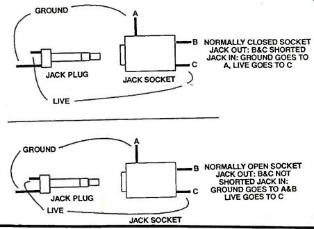
So, which type should you use? If you only want a regular ground and live connection, then either type will do-ground goes to 'a' and live goes to 'c'. Ignore pin 'b'. Radios, having earphone jack socket, that automatically disconnects the speaker when the earphone is in use, utilize the 'normally closed' type. Pin 'a' goes to ground, 'b' goes to the internal speaker and 'c' comes from the amplifier output. As we've said earlier, 'b' and 'c' are connected when there is no earphone connected. When you insert the earphone, 'c' is disconnected from 'b' and the live feed now goes from 'c' (coming from the amplifier output), through the jack plug to the earphone. Take time to follow this through and you shouldn't go wrong.
Nothing beats actually seeing for yourself, the differences between these components. All you need are two jack sockets (one of each type, 1/8"), a jack plug (1/8") and a regular ohmmeter.
DOUBLE DUTY JACK-SOCKET POWER SWITCH
There's nothing as neat as making a component do double duty and getting something for nothing! Here, we'll see how to get a jack socket to act both as a feed source into an amplifier and to also switch on the power at the same time. By pulling out the jack plug you not only disconnect the signal source but you also shut off the supply power-clever! This'll only work with what is called a `normally open' type of jack socket. This is a 1/4", three terminal jack socket. The input signal from the jack plug goes to pin 'c' and into the amplifier when the jack plug is inserted. The remaining two pins, 'a' and `b' are separated when the jack plug is not in. The normal ground connection goes to pin 'a', made when the jack plug is inserted. But. in addition, pin 'b' is also connected to 'a'. So we make use of this feature by, connecting the negative terminal of the battery to pin `b'. Hence, the only time a connection to the negative (or ground) terminal of the battery is made, is when the jack plug is inserted. Thus, we save having to use a separate switch. Where space is a premium, this tip could come in useful sometime. The illustration shows the `normally open' jack socket connections and how it is used in the way described here.
You can also use the same trick with the larger 1/4" jack socket/plug combo, as found with guitar amplifiers. These components are actually much easier to examine, being physically much bigger. Although shown, connected to the input of an amplifier, the jack socket can equally be connected to the output end. Just couple pin 'c' to the output as opposed to the input. The rest of the pins stay the same.

---------------------
CAPACITANCE METER
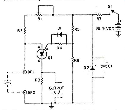
If you own a triggered-sweep oscilloscope or a frequency counter capable of making frequency measurements, you can use this PUT (programmable unijunction transistor) oscillator to measure capacitance. The practical range of measurement extends from 100-pF to about 10uF-wide enough to cover most of your measurement needs.
With an unknown capacitor connected across the binding posts, measure the time interval between output pulses on your scope or frequency counter. To convert time to capacitance, use the relationship: CAPACITANCE (uF) = 10 x TIME. For instance, a reading of 100-micro-seconds (.0001-sec.) indicates a capacitance of 0.001-uF (or 100-pF). (NOTE: 1-uF = 1,000,000-pF). To calibrate the oscillator, hook a 1000-pF polystyrene capacitor across the binding posts, and adjust R1 until the time between out-put pulses is exactly 100-microseconds.
PARTS LIST FOR CAPACITANCE METER
B1--9-volt transistor battery
BP1, BP2--binding posts
C1-100-uF, 10-VDC electrolytic capacitor
D1--1N914 diode
D2--1N752A, 5.6-volt, 1/2-watt zener diode
Q1--2N6027 programmable unijunction transistor
Note: All resistors rated 5% tolerance
R1--200,000-ohm trimmer potentiometer
R2--390,000-ohms resistor
R3--22-ohms resistor
R4--1 megohm resistor
R5, R6--2,200-ohms resistor
R7--560-ohms resistor
S1--SPST toggle switch
------------------
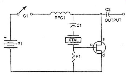
CRYSTAL OSCILLATOR
This JFET Pierce oscillator is very stable, very simple, and can prove very useful. With a suitable crystal, this oscillator can be the clock of a microprocessor, a digital timepiece or a calculator.
With as probe attached at the output, it can be used as a precise injection oscillator for troubleshooting. You can attach a small length of wire at the output to act as an antenna and use this circuit as a micro-power transmitter. With suitable crystals it can then provide reference marker frequencies for short wave listening, receiver tuneup, tv repairs and more.
Transistor Q1 can be a Siliconix 2N5458, a Motorola MPF102 or similar.
PARTS LIST FOR CRYSTAL OSCILLATOR
B1-6-15 VDC battery
C1-.001-.01-uF capacitor
C2-100-pF.001-uF capacitor
Q1--N-channel JFET (Junction Field Effect Transistor) (2N5458 or equiv.) R1--1-2.2 Megohm resistor, 1/2-watt
RFC1--Radio frequency choke, 2.5-mH
S1-SPST switch XTAL Crystal
-------------------------
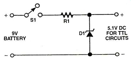
9V TO 5V POWER SUPPLY
The common 9V battery, useful for powering most transistor circuits, is too high for TTL logic. To power TTL logic, the 9V D.C. source can be lowered to a convenient 5.1 volts, using just two components. The positive 9V battery terminal is connected via switch S1, to resistor R1. R1 acts as a current limiter for reversed biased zener diode, (D1), When S1 is closed, D1 stabilizes to a useful voltage of 5.1V--just what is needed to power TTL logic.
PARTS LIST FOR THE 9V TO 5V POWER SUPPLY
S1-SPDT Switch
R1-100 ohm Resistor
D1-5.1V Zener diode (1N4733)
-------------------------
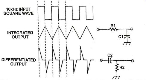
RC INTEGRATOR / DIFFERENTIATOR
The 555 timer is a nice, easy to use, source for generating square waves when connected in the free running astable mode. There are two very simple ways to 'modify' the stock square wave shape to produce what is called the 'integrated' wave and the 'differentiated' wave-the terms come from maths calculus text originally, but for electronics purposes, the end result is more of use than the calculus association. Begin with a stock audio frequency 10kHz square wave signal. The duty cycle does not have to be exactly 50%, i.e. the 'off' to 'on' periods are approximately the same, as seen in the diagram.
For the integrator circuit, the square wave feeds into a resistor, R1 and then a capacitor, C1. The values are chosen to 'match' the 10kHz signal. The output signal from the integrator resembles a sawtooth waveform and has several uses, either as a less harsh audio version of the square wave for use as a test signal generator or as a ramp type signal (this is more useful when the source signal is dropped down to the few Hz region), to monitor for threshold changes in comparator circuits.
The differentiator has the components reversed. The input signal is fed to capacitor, C2, followed by the load resistor, R2. The wave form here is totally different as seen. At each point where the input voltage changes state, a pulse spike is produced from the differentiator, first with one polarity then the opposite. These pulses can be used as trigger pulses or timing pulses and by using a rectifier diode either polarity spike can be selected. Experiment with the values to see what the changes do to the output.
PARTS LIST FOR THE RC INTEGRATOR/DIFFERENTIATOR
R1-1 K ohm resistor
C2-0.001 uF capacitor
C1-0.1 uF capacitor
R2-1 K ohm resistor
adapted from: Electronics Handbook Vol. X