(index locations on both: gammaelectronics.xyz and industrial-electronics.com)
If you want to extend your radio experience, your thoughts may turn to short wave. Buying a receiver can be expensive but with a converter you can use a medium wave radio.
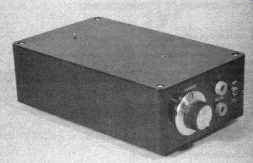
WHILE UNDENIABLY an interesting and challenging pastime, short wave listening can be an expensive hobby, with a new general coverage communications receiver costing typically a few hundred pounds. Even the lower cost types seem to command prices well into three figures. Fortunately, there are alternatives to purchasing a new communications receiver, and it is one of these that is explored in this article.
The unit described here is a short wave converter for use with any medium wave radio that has a ferrite rod aerial or some other form of built-in aerial. The basic set-up consists of a longwire aerial connected to the converter, with the converter placed close to the medium wave radio. The latter is tuned to a "quiet" frequency at the high frequency end of the medium waveband (about 1.6MHZ). This is important, since any station received directly by the radio will interfere with reception via the converter. Basically all that the converter does is to take in short wave signals and convert them to a frequency of around 1.6MHZ. The signals are then radiated so that they can be received by the medium wave radio.
This is admittedly a rather roundabout way of doing things, but it has the advantage of simplicity and low cost, with an existing medium wave receiver providing most of the circuitry. The converter itself can be extremely simple, and could be based on just a single active device. The level of performance obtained depends to a large extent on the quality of the radio, and not just on the performance of the converter. The effectiveness of the aerial is also an important factor. However, provided this converter is operated in conjunction with a reasonable aerial and a radio that gives good medium wave performance it should give good results when listening to short wave broadcast stations.
Although two amateur bands fall within the coverage of the converter it is not really suitable for amateur band reception because of difficulties in resolving the types of transmission normally found on these bands. The vast majority of short wave amateur transmissions are either SSB (single side-band) or CW (Morse) signals, neither of which can be received properly using an ordinary broadcast receiver with its AM (amplitude modulation) detector. This problem is not insurmountable and a crude form of SSB/CW reception can be obtained with a small amount of additional circuitry. In practice results are not likely to be very spectacular though, and this feature has consequently been omitted from this converter which is only intended for broadcast band listening.
The unit covers an approximate frequency range of 5 to 15MHZ. This provides coverage of the 25, 31, 39, and 49 meter broadcast bands, which, with the possible exception of the 25 meter band, will normally provide a number of interesting transmissions regardless of the time of day or year.
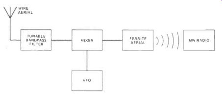
Figure 1. The block diagram of the shortwave converter. Note the final block is an ordinary MW radio receiver.
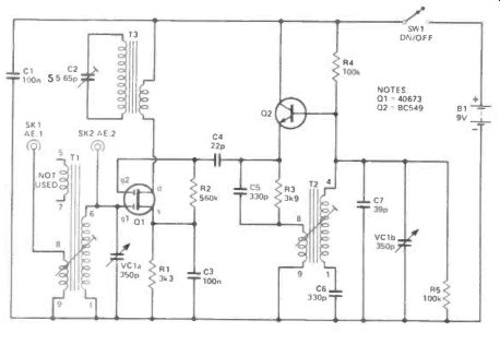
Figure 2. The Circuit. The full description of how the deceptively simple circuit works is overleaf.
Operating Principle
The shift in frequency from around 5 to 15MHZ down to about 1.6MHZ is obtained using the heterodyne principle.
This is something that is much used in radio circuits, and is almost certain to be utilized in the radio receiver with which you use the converter. Most radios are of the superheterodyne (or "superhet") type, where incoming signals are converted to a certain frequency, which is normally around 455 to 470kHz for MW/LW broadcast radios. This may seem to be a rather pointless and unnecessarily complex way of doing things, but for good radio reception high gain and a narrow bandwidth are required. These are easily obtained at a fixed frequency, but present real difficulties if a wide frequency range has to be covered. By converting incoming signals to a fixed ("intermediate") frequency and then processing the signal using a high gain selective amplifier a superhet circuit provides a level of performance that could probably not be achieved in any other way. When using the converter with a superhet medium wave radio there are two intermediate frequencies; one at 1.6MHZ and one at about 455 to 470MHZ. This produces what is called a "double superhet" or "double conversion" receiver.
The block diagram of Figure 1 helps to show the way in which the converter functions. The signal from the aerial contains numerous transmissions over a wide frequency range. The first stage of the converter is a tunable bandpass filter which attenuates signals at frequencies well outside the band that is of interest, but allows the wanted signals to pass. By removing most of the unwanted signals, gross overloading of the next stage of the converter is avoided.
This next stage is a mixer. It is important to realize, though, that this is not a mixer of the same general type used to mix audio signals. It is really a form of modulator, and the aerial signal is amplitude modulated by the signal from a variable frequency oscillator.
What is of importance in this application is the new frequencies that are generated at the output of the mixer.
These are the sum and difference frequencies. In other words, if an input signal is at a frequency of (say) 11.6MHZ and the VFO is operating at 10MHZ the difference frequency is 1.6MHZ (11.6-10 = 1.6). The sum frequency is 21.6MHZ (11.6 + 10 = 21.6), but it is normally the difference frequency that is exploited in converter circuits (and this is certainly the case here).
Signals 1.6MHZ above or below the VFO frequency will give the 1.6MHZ difference output frequency required in this application. The unit therefore receives simultaneously on two different frequencies 3.2MHZ apart, but in practice the input filter attenuates one response (called the "image") so that good sensitivity is only obtained at one frequency. In the majority of circuits, including the present one, the oscillator frequency is above the reception frequency, and the bandpass filter is used to attenuate the higher of the two responses.
Having obtained the required 1.6MHZ output signal it is necessary to couple it to the medium wave radio in some way.
Not all sets have a telescopic aerial or some form of aerial input socket, and radiating a signal that can be picked up by the radio in the normal way is a more practical and convenient way of doing things. What is required is a very strong signal in the immediate vicinity of the converter, but one that is insignificant more than a few feet away. Such a signal can be obtained using an ordinary medium wave ferrite aerial in reverse.
This effectively gives an inductive coupling to the aerial in the medium wave receiver, and a good signal transfer provided the two aerials can be placed within about 300 millimeters of each other, which is not normally difficult to accomplish in practice.
-------------------------
Parts List
RESISTORS
(All 1/4W 5% carbon) R1 3k3 R2 560k R3 3k9 R4, 5 100k CAPACITORS
01, 3 100nF ceramic C2 5.5-65pF trimmer C4 22pF ceramic plate C5, 6 330pF ceramic plate C7 39pF ceramic plate VC1 350pF + 350pF variable
SEMICONDUCTORS
Q1 40673 dual gate MOSFET
Q2 BC549 silicon npn
MISCELLANEOUS
T1
Denco Aerial coil for transistor usage range 4T (Blue)
T2 Denco 1.6MHZ dual purpose oscillator coil range 4 (White)
T3 Denco MW5FR ferrite rod aerial
SW1 SPST toggle type
SK1, 2 4mm sockets
B1 9 volt battery (PP3 size)
Plastic case about 180 by 110 by 55mm; PCB; battery clip; 'P' type cable clip to mount aerial; control knob: wire, pins, solder, etc.
----------------------------
Circuit Operation
The circuit uses just two active devices, as can be seen from the full circuit diagram which appears in Figure 2. As mentioned earlier, the heterodyne process can be produced using a single active device, but in the interests of good performance and low radiation from the VFO stage it is better to use separate active elements in the mixer and oscillator stages.
T1 is a radio frequency (RF) transformer, and the main winding on this forms a parallel tuned circuit in conjunction with one section of the two gang tuning capacitor, VC1. This tuned circuit forms the input bandpass filter.
The aerial is normally connected to SK1, and the aerial signal is then coupled to the tuned circuit via a small coupling winding on T1. If only a short aerial is used it might be better to use direct coupling to the tuned circuit, and this can be accomplished by connecting the aerial to SK2.
There is a third winding on T1 which would normally be used to couple the output of the filter to the base circuit of a bipolar transistor. In this circuit the mixer device is a dual gate MOSFET which has an extremely high input impedance at each gate input. This renders the coupling winding unnecessary, and it is left unused in this circuit. The g1 terminal of 01 is biased to earth through the main winding of T1, and R1 biases the source terminal slightly positive. This gives a small reverse bias to Q1, but this is a depletion mode device which requires such a bias to bring it into linear operation. R2 gives zero bias to the g2 terminal by taking it to the same potential as the source terminal. C3 is the RF bypass capacitor for R1. This prevents R1 from introducing negative feedback which would give low gain from Q1.
The gain of Q1 from the g1 terminal to the drain circuit can be varied by means of a voltage applied to the g2 terminal. In this case the g2 voltage is varied by the signal from the VFO which is coupled to Q1 via DC blocking capacitor C4. The sum, difference, and all input frequencies appear in the drain circuit of Q1. However, the ferrite aerial (T3) selects and radiates only the required 1.6MHZ difference signal, and the medium wave radio will, of course, only respond to this signal anyway. C2 enables T3 to be peaked at precisely the frequency to which the medium wave radio is tuned so that optimum coupling is required. The output of Q1 is coupled to T3 via its low impedance coupling winding so that an efficient coupling is obtained.
The VFO is a perfectly straightforward L-C oscillator which uses Q2 in the emitter follower mode. An emitter follower stage provides slightly less than unity voltage gain, but T2 provides the voltage step-up that is needed to sustain oscillation. C6 is the "padder" capacitor.
As the oscillator is tracking 1.6MHZ above the reception frequency the tuning capacitance swing for T1 needs to be different from that for T2. As the oscillator operates at a generally higher frequency range it needs a smaller tuning capacitance range. The padder capacitor is in series with the oscillator tuning capacitor (VC1 b) and effectively reduces its capacitance swing. The value of C6 is chosen to give good tracking between the aerial and oscillator tuned circuits.
Power is provided by a small 9 volt battery. The current consumption of the circuit is only about one milliamp and each battery gives many hours of operation.
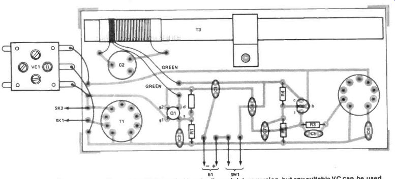
Figure 3. The component layout. VC1 as specified is actually a miniature version, but any suitable VC can be used.
Construction
Most of the components, including the two coils and the ferrite aerial, are mounted on the printed circuit board.
Figure 3 shows the component layout and wiring. A number of points need to be kept in mind when building the board.
The ferrite aerial (T3) is mounted on the board using a large (about 9 or 10mm) 'P' type cable grip. This, together with the aerial assembly, is bolted to the board using a short M3 or 6BA bolt and fixing nut. There should be no difficulty in identifying the leads from the two windings of T3 correctly since the main winding is made using standard pink colored litz wire, whereas the small winding is made from green colored wire. Litz wire can be a little difficult to deal with, but things are made easier here as the leadouts are ready-tinned with solder. Trim the leadouts slightly so that only a short length of tinned wire is left at the end of each lead. This reduces the risk of accidental short circuits. Do not trim the leadout wires back any further than this. Position the coil almost at the end of the ferrite rod.
Q1 is a MOSFET device, but it has built-in diodes to protect it from high voltage static charges. Antistatic handling precautions are therefore unnecessary when dealing with this device.
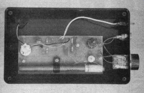
T1 and T2 are really intended for plug in mounting in a B9A valveholder rather than printed circuit mounting. The pins at the base of each former will plug into the board without too much difficulty, but they could be a little awkward to solder to the board properly. It is advisable to clean the pins of each coil by scraping them with the small blade of a penknife before fitting the coils onto the board.
This should make it much easier to obtain strong and reliable soldered joints.
A plastic case having dimensions of about 180 by 110 by 55 millimeters is suitable as the housing for this project. In fact a somewhat smaller case could be used if desired, but the case must not be of metal construction as this would screen the ferrite aerial and prevent the 1.6MHZ output signal from being radiated. The printed circuit board is mounted on the base panel of the case using M3 or 6BA fixings. As the pins of T1 and T2 protrude several millimeters on the underside of the printed circuit board it is advisable to use spacers over the mounting bolts between the case and the board. If this is not done it is likely that the board will be distorted and it could possibly crack as the mounting nuts are tightened.
VC1 and the two sockets are mounted on the front panel, which is one of the 110 by 55 millimeters panels of the case.
VC1 is supplied with two mounting screws which can be used to fix it to the panel, or it can simply be glued in place using a good quality general purpose adhesive. There are several tags on VC1, but in this case it is only the three at the front of the component that are required. Of course, any twin gang variable capacitor having a maximum value of about 310 to 375pF per gang can be used in the VC1 position, but the specified component is almost certainly the least expensive type currently available.
To complete the unit the small amount of hard-wiring is added. As supplied the cores of the coils are almost fully screwed down. Unscrew the cores so that about seven or eight millimeters of metal screw thread protrudes from the top of each coil. Unless you use a very large case it is unlikely to have sufficient "headroom" to accommodate the coils with the cores adjusted in this way, and two small holes must be drilled in the lid of the case so that the screwthreads can pass through. This may not look terribly neat, but it does enable the cores to be adjusted without having to remove the lid of the case.
Aerial A suitable aerial for the converter simply consists of a length of aerial wire which should be as long as possible and strung as high as possible. Ideally the aerial should be an outdoor type of about 20 to 40 meters in length and placed well clear of buildings. One end connects to the converter and the other is left free. In practice few people are able to accommodate an ideal aerial, and it is usually a matter of doing the best one can under the prevailing circumstances.
Even a few meters of ordinary multi-strand connecting wire mounted indoors will provide reception of many interesting stations, but equally such an aerial is not going to give the best results obtainable from the equipment.
You might like to try adding an earth connection. This is by no means essential, but can give a useful improvement in results. An earth consists of a piece of metal buried in the earth, and connected to the negative supply rail of the converter (an extra socket on the front panel wired to the negative supply rail will be needed if you decide to use an earth). A length of metal pipe or rod makes a reasonably efficient earth that is easy to install. Keep the lead from the earth to the converter as short as possible.
Adjustment and Use
First tune the medium wave radio to the high frequency end of the medium waveband and search for a setting that is free from stations. You should be able to find a suitable setting even after darkness has fallen (when the MW band provides reception of a vast number of stations), and remember that the directional aerial of the radio enables it to be turned to null any received signal.
With the converter switched on and placed alongside the radio it will probably be possible to receive a few short wave transmissions. If not, try C2 at various settings until some signals are received. The best signal transfer from the converter to the radio is obtained when the ferrite rod aerials are parallel to one another and as close together as possible.
Once a few stations can be received, adjust C2 to peak performance. The bandwidth of the ferrite aerial is quite narrow and C2 should give a sharp peak.
By contrast, T1 has a very wide band width, and the setting of this will be relatively uncritical. It is given any setting that gives good results over the full frequency range covered.
You might like to try making one or two simple improvements to the basic converter. An aerial trimmer control can be added by connecting a variable capacitor of about 50pF in value across VC1a. With the core of Ti at a suitable setting this enables the input filter to be peaked for optimum results at any setting of the tuning control. A bandspread control can be added by connecting a variable capacitor of about 25pF in value in parallel with VC1b. This only gives coverage of a narrow range of frequencies, but fine tuning is consequently very much easier using the bandspread control. If no bandspread capacitor is fitted it is advisable to fit VC1 with a large control knob.
--------------
Shop:
There are one or two 'interesting' components in this one.
The Denco parts are available from Electro-value (Tel: (0784) 33603). The blue aerial coil is listed at £ (x 1.4 USD) 1.86. the white dual purpose coil at £ (x 1.4 USD) 1.42 and the 5FR / MW rod aerial at £ (x 1.4 USD) 1.43.
Electrovalue also list an Altai variable capacitor (miniature) of Oho 350pf at £ (x 1.4 USD) 1.35, which is considerably cheaper than the average VC, and a trimmer capacitor (C2) of the right specification for 37p.
The other parts should present no puzzles, and the overall cost of the project should be around £ (x 1.4 USD) 11 using the parts mentioned, excluding a case of your own choice, and PCB.
-------------
Also see: Link |