Our descrambler starts to take shape.
by ROBERT GROSSBLATT
For reasons that I've never understood, even people who manage to build circuits of mind boggling complexity turn green at the gills when it comes to designing circuits that can manipulate baseband video. Maybe its due to the complexity of the signal or the speed of some of its components (in the single-digit microsecond range), but lots of very talented circuit designers tend to shy away from anything but the most basic video circuitry.
Building a circuit that can make sense out of SSAVI encoded signals isn't simple, but it's not impossible, either. Best of all, it can teach you a tremendous amount about basic video, too. We've reached the point in this subject where we start turning to hardware. If you look over the block diagram in Fig. 1, you'll see that the circuit we'll need is no more complex than any of the others we've put together over the years.
The final thing we talked about last month was a reset pulse that's needed to initialize the various line counters that will be part of the SSAVI descrambler. We need to find something in the scrambled signal that's stable enough to use as a reset for our digital circuitry.
Remember that everything in the vertical interval is sent "in the clear." One of the components there is vertical sync-an ideal candidate for generating a reset pulse.
When you look at scrambled video on a scope or waveform monitor, you may wonder how anything can be picked off the signal. (Incidentally, you stand a much better chance of successfully viewing the scrambled signal if you have a dual-channel scope. Just feed standard video into one channel, use that for the trigger, and view the scrambled stuff on the other channel of the scope.)
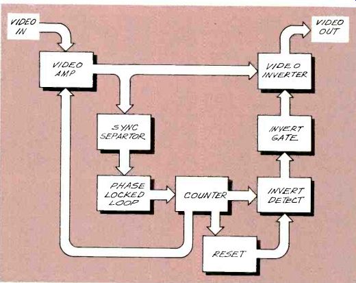
FIG. 1-BLOCK DIAGRAM OF OUR SSAVI DESCRAMBLER. The individual sections
of the circuit are no more complex than other circuits we've put together
over the years.
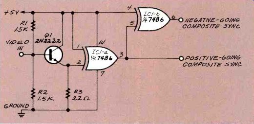
FIG. 2--THIS CIRCUIT WILL TAKE VIDEO in at one end and give you positive
and negative-going composite sync signals at the other end.
Scrambled video may look like a mess, but even broadcast video that's sent in the clear is incredibly jittery. It's a tribute to TV designers and the video standard in general, that the TV set can lock onto anything that comes in over the airwaves.
If you tune your TV to a scrambled signal, you'll note that although the picture is messed up, the screen always shows a full frame. That's because, even though horizontal sync has been altered by the cable company, vertical sync can still be recognized by the circuitry in your TV. The first piece of hardware we built some months ago was a simple demonstration circuit that enabled you to mess up the horizontal sync signal. I hope you haven't thrown that away just yet because we can use part of it now. The first thing we have to do to the video signal to descramble it is separate the sync from the picture.
The circuit shown in Fig. 2 will take video in at one end and give you two versions of the composite sync part of the signal out the other end: positive- and negative-going.
The transistor is working as a simple buffer and, by adjusting the video level at its output, we can have the incoming negative sync fall below the high threshold of the TTL Exclusive-OR (XOR) gate. The first gate produces the composite sync and the second gate works as a simple inverter.
If this is the first time you've seen this circuit, you can get a full description of it by going back to the November 1992 column where it appeared for the first time. There are other ways to separate sync, but this one has the advantage of giving you an output that swings close to the supply rails, has a very low noise component, and is at TTL logic levels, which makes it much more reliable for feeding the digital circuits we'll be designing for the rest of the descrambler.
While we're looking at the composite sync signal, this is a good time to work out the details of the reset circuit since it has to isolate vertical sync from the composite sync signal. The way to do that should be obvious when you look at Fig. 3, the composite sync waveform. Just as it's supposed to be, vertical sync is the most negative part of composite sync. To isolate the vertical sync, we need a simple low-pass filter; a suitable one is shown in Fig. 4.
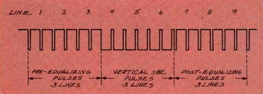
FIG. 3--COMPOSITE SYNC WAVEFORM. Vertical sync is the most negative
part of composite sync.
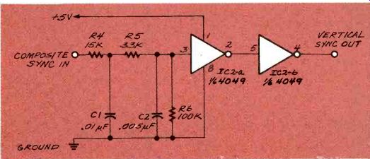
FIG. 4--TO ISOLATE VERTICAL SYNC, we need a simple low-pass filter
like this.
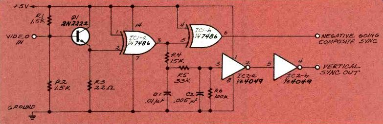
FIG. 5--THE FINISHED PIECES OF OUR DESCRAMBLER can be put together
as shown here. Video goes in at one end and we're able to isolate
the sync pulses at the other end.
The two gates after the filter clean up the sloppy waveform produced by the R-C circuit. You'll notice that CMOS 4049 inverters square up the shoulders of the waveform. The low-pass filter (or vertical integrator, as it's sometimes called) is being fed with a positive-going version of composite sync and, since it's going through two inverters, it's producing a positive-going vertical sync pulse at the output of the circuit.
That's necessary because we a positive-going vertical sync for the rest of the circuit. As with most things electronic, there are several ways to do the same job, but bear with me until we've gone through the whole design before changing things around. Once you understand the circuit in its entirety, you can start modifying it to your heart's content.
Even though we haven't completed the design of the descrambler yet, the pieces we've finished can be put together as shown in Fig. 5 to produce some interesting and extremely informative waveforms. Video goes in at one end and we're able to isolate the sync pulses at the other end. I leave it to you to imagine what a bit of creative gating can do--especially if you use these signals to control the switches in a 4066 as we did some months ago in the demonstration circuit.
Now that we have vertical sync isolated, the next job to do (and the most critical for the descrambler) is to come up with a way of producing horizontal sync. That is obviously more difficult because we know that it won't be present all the time in the received video signal. As a matter of fact, it's a lot better if we operate under the assumption that it's never there at all.
Generating horizontal sync pulses is, in and of itself, a fairly simple business. We know the pulse width and frequency we need for it, but we're missing the starting point. There has to be some reference somewhere in the signal that we can identify so we know how to establish the correct time relationship between our artificially generated horizontal sync pulses and the received video signal.
The answer to this is the same one we've found all along-again don't forget that video is sent in the clear during the vertical interval. If you look there you'll find 26 lines of normal video with normal horizontal sync pulses. That gives us 26 lines of reference signals. Our job is to design a circuit that will continue to produce horizontal sync at the same rate and at the same interval for the rest of the frame.
Because there are 260 or so lines in each frame of video, we'll have a reference available for about ten percent of the time. That's more than enough of a reference for a well-designed phase-locked loop circuit to maintain the correct repetition rate for horizontal sync throughout the entire frame. As we pointed out some months ago, the color-burst signal is present for only 2.5 microseconds, and it serves as a reference for 53 microseconds of picture on each video line. That means the color reference is around for less than four percent of the time. Since we'll have a reference for more than twice that time for horizontal sync, we shouldn't have any problems.
The key to getting good video from a SSAVI encoded signal is the design of the phase-locked loop that will generate the missing horizontal sync pulses and put them on each video line at exactly the right time. Next month we'll see what has to be done to design that part of the circuit.
There's some math involved and we'll be using a 4046 CMOS phase-locked loop as the heart of the circuit. Get yourself a data sheet on the chip because using it is a bit more involved than the standard gates and counters in the rest of the circuit.
-R-E