High-side FET drivers, drawing semilog plots, resonance fundamentals, laser printing repair kits, and Asian electronic sources.
by DON LANCASTER
A few additional comments on the correlation from back in our August 1992 column. Our third autocorrelation mask example obviously should have been 0010 rather than the typo shown.
I should have stated "Radar range depends upon transmitted pulse energy" rather than "is proportional to." Doubling the transmitted radar pulse energy typically can extend effective range by only nineteen percent.
Good classic texts on radar include Merrill Skolnick's Radar Handbook, and the hoary "Rad Lab One" which refuses to die otherwise known as Radar Systems Engineering by Louis Ridenour. Another very outdated but popular introduction is Robert Page's Origin of Radar from Doubleday.
While much of the information on chirp-radar techniques is classified or otherwise hard to locate, the Theory and Design of Chirp Radars in the Bell System Technical Journal of July 1960 is a good introduction.
I've also got a summary in my January 1965 Electronics World chirp story. More current information can be found through the Dialog Information Service.
Several readers questioned the synchronous rectification example circuit. Yes, this is correct as shown. And, yes, there is one hidden "gotcha." When a MOS power transistor is used as a synchronous rectifier, it is run in its third quadrant.
Not the first quadrant as you might initially expect. That's done to keep the substrate diode from shorting out the works. More on this subject below.
Additional details on synchronous rectifiers appear in that Mos-Power Applications Handbook by Siliconix and in those Motion, Motion Control, PCIM, or Power Techniques magazines.
Fundamentals of resonance
Resonance is certainly one of the most interesting and important electronic concepts. But there sure seems to be lots of helpline confusion over what resonance can and cannot do. Yes, you can produce incredible energy buildups in certain resonant circuits destructive and even lethal ones. Yes, you can extract this energy if you want. No, none of the stored resonant energy is "free." Just as in a piggy bank, you cannot take more quarters out than were put in. One hundred percent of all earlier attempts at "free" resonant energy have failed miserably. Let's take a fresh look at resonance fundamentals... Figure 1 shows the simple series combination of a resistor, an inductor, and a capacitor. This is a series resonant circuit. Assume for now that the resistance is your load, the inductor and capacitor are very high quality, and the signal source is a very low impedance.
At extremely low frequencies, the inductor will look like a short circuit and the capacitor will appear as a very high capacitive reactance. Very little signal will reach the load.
Similarly, at very high frequencies, the capacitor will look like a short circuit, and the inductor will appear as a rather high inductive reactance. And once again, very little signal will reach the output load resistor.
At one specific frequency, though, both of the inductive and NEED HELP? Phone or write your Hardware Hacker questions directly to: Don Lancaster Synergetics Box 809 Thatcher, AZ 85552 (602) 428-4073 capacitive reactances will be equal in magnitude and opposite in sign, and will cancel out to zero, transferring all of the input signal to the output load. This "magic" frequency is defined as the resonance frequency.
As Fig. 1 shows us, the resonance frequency is determined by the product of its L and C values.
Resonant circuits are often frequency selective. They allow you to tune to a chosen frequency. This is how you select any particular AM or FM radio station while you tune out all of the others. Resonant circuits can also store surprisingly large quantities of energy. One very important energy storage use for resonant circuits is in the deflection circuitry of television sets and computer monitors. Sneaky resonant switching tricks are used to sweep the beam back and forth while recycling the available energy.
The "Q" of a series resonant circuit can be defined in several unique ways. Q (standing for quality) could be defined as the ratio of the resonant inductive reactance to the load resistance. Or as the bandwidth between the 3decibel half power points. Or as a function of the ringing decay time. Or as the amount of the resonant voltage increase obtained across the inductor or capacitor. Or as the ratio of the stored to the dissipated energy per cycle.
All of the Fig. 1 definitions of Q are identical, but they will lead you to profoundly different redundant applications for resonant circuits.
You can change the resonant frequency by shifting the LC product.
You can also change the Q by shifting the LC ratio.
Figure 2 shows exactly how the response of series resonant circuits will change with frequency and Q. The higher the Q, the narrower the final bandwidth between the half power (or 0.707 voltage amplitude)
points. Note that each of these curves starts out by rising at +6 decibels per octave, swings up through a sharp resonance peak, and then eventually ends up falling at a-6-decibels-per-octave rate.
No matter how steep the near-resonance drop off, it reaches a point where either the inductor or the capacitor reactance is too small to make much difference.
If you need more attenuation well away from the resonance frequency, you usually are better off adding extra series-resonant poles, or otherwise cascading poles.
You can quickly sketch most resonant curves. You should get zero attenuation at the center frequency, and 3 decibels of attenuation at the half-power bandwidth points set by 1/Q. You can then locate the resonant frequency point Q (converted to decibels down) and sketch a pair of 6 decibel–per-octave lines on down from there. Then smoothly connect all of the dots and the lines.
In high-Q series-resonant circuits, the usual reactive voltage across the inductor or capacitor will be many times that of the input. For instance, a 1-volt input at resonance and a Q of 100 will produce a nasty 100 volts across the capacitor or the inductor. Some switching-mode power supplies make use of this resonant rise for a transformer-free voltage increase.
The resonant voltage step up can easily become destructive if the input signal becomes too big.
Just as a pendulum swaps kinetic for potential energy as it oscillates, the inductor stored L/2 /2 energy is at a maximum on current peaks, and the capacitor stored CV2 /2 energy is at a maximum on voltage peaks.
While the energy appears to swap back and forth between inductor and capacitor, the total stored energy over any one cycle remains constant.
-------------------------
The RESONANCE FREQUENCY occurs whenever both the inductive and capacitive reactances are equal...
The AMPLITIUDE RESPONSE defines the ratio of the input to the output voltage, expressed in decibels...
The Q or QUALITY FACTOR is defined in several different ways, each of which leads to a different application... (A) As the reactance to resistance ratio...
(B) As the half power bandwidth...
As the inverse of the damping...
As the resonant voltage rise... (resonant voltage across L or C)
(resonant voltage across R)
As the ringing rundown time... A resonant circuit decays to 1/E amplitude (or 37% =-8.7 decibels) in Q/n cycles.
As the stored energy ratio... 2n (energy stored per cycle)
(energy dissipated per cycle)
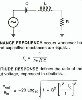
FIG. 1--AN RLC SERIES RESONANT CIRCUIT forms the basis for many electronic
tuning, filtering, voltage step up, and energy storage circuits.
But there is no way I know that it can produce "free" energy.
Let me know if you find one.
----------------------------
One definition of Q is 2 pi times the energy stored per cycle divided by the energy dissipated per cycle.
Thus, if you have a Q of 100, a 1-amp input, and a 1-ohm load, at series resonance it will dissipate 1 watt per cycle while it stores around 15.9 watts per cycle.
Just where did the 15.9 watts come from? The same place the stash in the piggy bank came from.
It was built up earlier, a quarter at a time. During the transient intervals when you first apply a signal, input energy will slowly be saved, building up the inductor and capacitor energy storage.
Very large amounts of energy can be stored in resonant circuits. In the case of a large color TV or computer monitor, as much as 5 kilowatts of resonant power is involved in the horizontal sweep circuitry-in a very efficient circuit that continuously recycles resonant deflection currents. More on this in the Hardware Hacker III reprints.
If you deliver an impulse to a high-Q resonant circuit, it will ring for a rundown time as shown in Fig. 1.
The higher the Q, the longer the ringing time. One obvious use is in electronic chimes and gongs.
Although I have shown a single resistor in our resonant circuit, it really has a load resistor, a source-impedance resistor, and the resistive losses in the inductor. All of these have to be accounted for in the real world. For a series resonant circuit to operate, it must be driven from a very low impedance source.
You can also create the dual of this RLC circuit by placing everything in parallel, creating a parallel resonant circuit. Any parallel resonant circuit reaches a very high impedance at its resonance and operates only when it is driven from a very high impedance current source. Instead of voltages multiplying by Q, the reactive current multiplies by Q instead.
More on resonance fundamentals appears in most electrical engineering texts such as Skilling's Electrical Engineering Circuits. And lots more on working with and using resonant circuits appears in my Active Filter Cookbook.
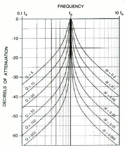
FIG. 2 EXTENDED RESONANCE RESPONSE CURVES for a series RLC circuit. Note
the "flattening out" for frequencies well away from resonance.
PostScript to the rescue At one time, drawing camera-ready charts and graphs like Fig. 2 was a real hassle. First you had to find some semi-log paper, and then trace it to the correct resolution.
Then you had to calculate all of the needed points.. Finally, you had to ink them with splines or French curves, messy pens, and similar drafting tools. Final size and detail changes were a real bear. Especially if you had to stretch or shrink it in one direction only.
Even then, the editor might decide it's not good enough and redo the entire figure from scratch.
These days, instead, you simply use that superb PostScript language to draw the whole job for you-instantly and hassle-free.
PostScript is one totally general purpose and super friendly computer language that is absolutely ideal for many hardware hacking tasks.
One of PostScript's utterly minor and almost insignificant capabilities is to dirty up clean sheets of paper.
In any way you like. Totally device independently. So the same old word processor text file you use for your rough proof copy can also be photo-type set interchangeably, on any brand of personal computer that you might want to use.
Figure 3 shows the ultra simple PostScript code required to create all the fancy semi-log decibel resonance plots that you see in Fig. 2.
You just shove this through your favorite word processor and then send it to a PostScript printer with a two-way communication setup. Ethernet, AppleTalk, Serial, or Shared SCSI!, communication all seem to work just fine.
I have just posted a PostScript for Hardware Hackers tutorial as #511 NUTS9.PS to my GEnie PSRT. Among the many hundreds of other PostScript –as language files, the full Smith Chart drawing routines as file #367 SMITHCHT.PS and my printed circuits as #401 PRINCRCT.GPS. The PostScript startup secrets tutorial now appears as #335 SECRTEMP.GPS and PostScript speedup secrets tutorial as #460 SPEEDUP.PS. Unique PostScript code to let you instantly draw all the camera-ready figures in this column appears as HACKFG59. PS. Finally, if you do not now have a PostScript printer, I've posted the GHOSTSCRIPT files to PSRT. These let you run PostScript with just about any printer. They also give you full viewable display PostScript on any monitor. The current PSRT banner shows you the latest Ghost-Script version numbers to use.
While Fig. 2 can easily be done in "raw" PostScript, I've made things even faster and simpler by opening the convenient and powerful layout/ illustration dictionary that I use. This file is #517 GONZO15.PTL and is persistently downloaded at the start of your work session. One single "guru" command opens up this set of power tools for you.
You can also write or call me for a free new PostScript secret resources mailer.
---------------
Requires persistent download of GONZO15.PTL utility from GEnie PSRT. guru save / snapl exch def 200 300 10 setgrid % 30 30 showgrid linel 1 setlinecap 10 0 mt 26 u 0 0 mt 26 pu 20 pr 26 pd 20 pl gsave linel stroke grestore gsave clip newpath 0 setlinewidth 0 setgray 1 1 10 (log 10 mul 0 moveto 0 28 rlineto stroke) for 10 10 100 (log 10 mul 0 moveto 0 28 rlineto stroke) for 0 2 28 (0 exch moveto 20 0 rlineto stroke) for
/fnc (dup dup mul 1 sub exch div dup mul Q dup mul mu! 1 add sgrt log 20 mul neg) def
/vsf (2.5 div 26 add) def /hsf (log 10 mul 10 add) def /incperdec 200 def /startat 0.1 def
/wholecurve { /Q exch def newpath /val startat def val dup Inc mt incperdec 2 mu! 1 add {val fnc vat hst exch vsf lineto /val val 10 1 incperdec div exp mul def] repeat 0.06 setlinewidth stroke} def (5 10 20 50 100 200] (wholecurve) fora!! grestore
/cstretch 0.01 def /sstretch 0.03 def /yinc 1 def
/fonts /Helvetica 0.85 gonzofont
/font2 /Helvetica-Bold 0.85 gonzofont
/font3 /Helvetica 0.7 gonzofont
/ font4 /Symbol 0.75 gonzofont
/font5 /Helvetica (0.7 0 0 0.7 0-.2] gonzofont
/font6 /Helvetica (0 0.85-0.85 0 0 01 gonzofont
/b+ (gsave newpath /msg exch def translate 40 rotate 1 setlinecap white 0.8 setlinewidth font3
0 .3 mt msg stringwidth pop 0 add r black 0 0.1 msg cl grestore) def
/b(gsave newpath /msg exch def translate-40 rotate 1 setlinecap white 0.8 setlinewidth font3
0 .3 mt msg stringwidth pop-1 add 1 black 0 0.1 msg cr grestore) def /kern 0.1 def fonti 10 28.3 (FREQUENCY) cc-3.3 8 (16DECIBELS OF ATTENUATION) cl ((linel 0 26 mt 0.5 u) 10 3] xrpt [ {line] 0 2 mt 0.5 I) 4 7] yrpt
0 26.9 (0.Iki fl5o) cc 10 26.9 (115o) cc 20 26.9 (11k0 fl5o) cc 1 13.6 (0 = 5) b+ 1 11.2 (Q = 10)
b +18.8(Q =20)b+ 1913. 6( 14013f= 0.2)b1911.2(14013f= 0.1)b-19 8.8(140131 =0.05)b195.6(14013f= 0.02)b193 .2(14013f= 0.01)b190.8(14D13f= 0.005) b1 5.6 (0 = 50) b+ 1 3.2 (0 = 100) b+ 1 0.8 (Q = 200) b+ fonti-.8 25.7 (0) cr-.8 21.7 (-10) cr-.8 17.7 (-20) cr-.8 13.7 (-30) cr-.8 9.7 (-40) cr-.8 5.7 (-50) cr-.8 1.7 (-60) cr snaps restore show page quit
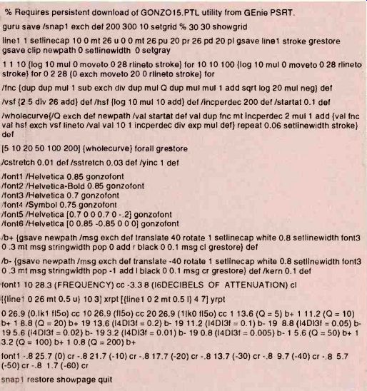
FIG. 3--GURU GONZO POSTSCRIPT CODE used to create camera-ready semilog
artwork for Fig. 2. Only your favorite word processor is needed!
-----------------
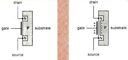
FIG. 4--THE N-CHANNEL POWER MOSFET is now the most popular and most economical
power switch in use today. Increasing the gate voltage above its
threshold value turns the device on.
High-side drivers
There's a new game in town called high-side drivers that are becoming super important. A high-side driver is a solid-state relay placed between the positive DC supply line and any circuit loads that you wish to control.
Automotive people like high-side drivers because only a single wire is needed for each load; the chassis forms the ground return. Laptop and palmtop computer folks like high-side drivers because the inputs and outputs of the controlling circuits are not hurt by any floating grounds.
Many high-side drivers are smart enough to protect themselves against shorts, overloads, and other faults. What gets tricky fast about high-side drivers is that the preferred choice in any electronic switch today is the N-channel power MOSFET. To turn on an N-channel MOSFET that's connected to a positive supply voltage, you need a gate control signal well above that of the positive supply.
Before we see just how we can get a control signal that is well above that of the most positive supply line, let's briefly review just what an N-channel MOSFET is and how it works. Fig. 4 shows details.
You start with a block of P-doped silicon known as the substrate. Add a non-rectifying or an ohmic terminal to it. Now you implant two N-channel wells in the substrate. Add ohmic contacts to these and call them the source (on the bottom) and the drain (on top). Now, build a capacitor by adding a super-thin dielectric layer and a conductor between the source and drain. Call this lead the gate.
If the gate is at a zero or negative potential with respect to the source, there will be a zero drain-to-source current, (the MOSFET looks like a pair of back-to-back diodes). There will also never be any steady-state gate current, because all the gate does is charge or discharge a small capacitor.
Let the gate become somewhat positive with respect to the drain.
Electrons have to pile up on the substrate side of the gate capacitor, so that area will become less of a P-type material. Let the gate voltage exceed a threshold value, and the extra electrons on the substrate side will actually change the substrate into a continuous N channel between source and drain. We now have three N regions tied together into a solid block. These look like a plain old resistor and allow current to pass between source and drain.
Below the threshold voltage, there will be an open circuit between source and drain. Above threshold, there will be a small resistor between source and drain. A grounded gate turns it off. A gate above the threshold voltage turns it on. The typical threshold is around +4 volts or so, but to turn the device solidly on, a gate-to-source voltage of +10 volts is preferred.
Unlike the NPN power transistors, there are no saturation effects or PN junctions in the main current path. There is also zero steady-state gate current needed.
A MOSFET that is turned on acts as a plain old low-value resistor.
The "on" resistance of a single N-channel MOSFET isn't really that great. For instance, in the CMOS 4066 quad analog switch, the on resistance is a high 16 ohms or so.
To beat that, power MOSFETS are made up of hundreds, or even thousands of tiny MOSFET transistors all internally connected in parallel.
There are lots of sources for power MOSFET chips. Motorola, Siliconix, Texas Instruments, and International Rectifier are some. Because of their quite low cost and high gain, MOSFET's have become the main power switch of choice for many electronic uses. Although there are also P-channel MOSFET's, they cost more and are less efficient. And because of certain fundamental device physics, they are likely to remain so.
Since a power MOSFET turned on is really nothing but a resistor, it does not matter which direction the main current goes. If you do the obvious and make the drain go positive with respect to the source, it is said to be in quadrant I. If you make the drain negative with respect to the source, you end up in quadrant Ill. High-side drivers work in quadrant I. But most synchronous rectifiers that use MOSFETS normally run in quadrant III to avoid substrate diode conduction.
To use an N-channel MOSFET as a high-side driver, just connect the drain to the positive supply, and the source to the load being controlled.
To turn the switch off, leave the gate at or below the positive supply voltage. To turn the switch on, connect the gate to a value well above that of your positive supply, typically by +10 volts or so.
A number of new low-cost integrated circuits are now available that use charge pumps and similar circuit tricks to let you reliably apply N-channel MOSFETS as high-side power switches. Typical examples include the International Rectifier IR2125, the Maxim MAX620, and the Linear Technology LTC1155.
The LTC1155 is a very interesting device. It has a self-protecting pair of micropower dual high-side drivers in a single eight-pin mini-DIR. A dual high-side circuit breaker is shown in Fig. 5.
Here is how either half of this circuit works: A built-in charge pump continuously generates a reference voltage above the positive supply.
Leaving IN1 low leaves the load unpowered. Raising IN1 to a TTL logic one ( + 2 volts or higher) supplies the boosted voltage to the power MOSFET, turning on the load. With a 5-volt supply, the boosted voltage is around +12 volts total, or around+ 7 volts above the supply. Higher boost voltages are generated for higher value supplies.
The load power normally stays on until IN1 drops to a logical zero under 0.8 volts. There's also a protection input known as DS1. If DS1 ever gets more than one tenth of a volt below the supply, it automatically shuts things down. You can add a load sensing resistor of one tenth of an ohm per amp to shut down on any overcurrent, as shown.
Some loads might have large but expected inrush currents. This often happens with incandescent lamps and solenoids. A resistor and capacitor time delay can be added to the current sensing to allow inrush currents but still react to overloads. This simulates the operation of a slow-blow fuse. See the LTC1155 data sheet for details.
Switching times are fast but not stunning. The turn-on time is around half a millisecond. The usual turn-off time is around 32 microseconds.
Note that any simple EXCLUSIVE-OR gate could be used for external fault detection. If the on command is high and your load is low, you will have an output short. If the on command is low and the load is high, you will have an output open. If both are low, you have a normal switch turn-off, and if both are high, you'll have a normal switch turn-on condition.
The standby current when off is a mere 8 microamps, making this ideal for battery-saving applications.
More semiconductor houses
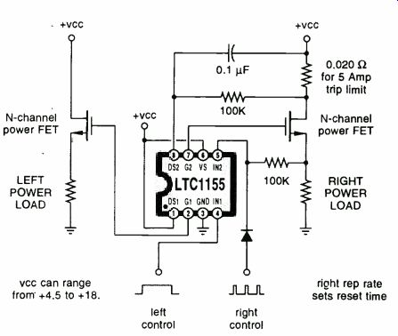
FIG. 5--A DUAL HIGH-SIDE DRIVER. The left side is shown as a simple
power relay, while the right side includes "slow blow" current
sensing and an automatic circuit breaker reset. Boosted gate voltages
are internally generated.
This month we will continue our multi-part resource sidebar listing of semiconductor houses, picking up Gould through NEC. I have left off some of the more obscure outfits that don't seem too innovative.
General Electric, Intersil, and RCA are now part of Harris. A few of their better chips remain available.
Similarly, the Sprague folks have now become Allegro, Amperex has sold out to Philips, and the dregs of Mostek were long ago absorbed into SGS. General Instrument has moved across the country and all their good sound-effects chips fell off the truck on the way. Most of the low volume power semiconductor houses are now changing their names so fast it is hard to keep up.
See PCIM and similar trade journals to find just out who is currently calling themselves what.
Laser repair training bargain Canon Inc. manufactures the most popular laser printer engines in use today by far. Hewlett-Packard, Apple, QMS, and many of the other major players all use Canon engines in their laser printers.
Of these printers, by far the most popular mid-range units all include the Canon SX engine. And the largest single repair cost on all these machines is cleaning and repair of the SX fusion assemblies.
The things that typically goes wrong with SX fusion assemblies are scored or swollen rollers, broken or burned-out quartz heater lamps, worn gears or those with missing teeth, dirty or defective temperature sensors, feed creasing and jamming, or general grunge accumulation.
Don Thompson of Techni-Graphics has long offered the very finest laser-printer repair training. He recently sent me a sample of his new SX Fuser Assembly Master Kit, and has agreed to offer it to Electronics Now readers at a special price of $350. For the price of one new fusion assembly or one single fusion repair from a typical computer dealer, you get a complete set of all the quality hand tools and supplies required to become a fusion rebuilding expert; a two-hour lucidly detailed videotape; secret insider info on the "tye wrap" spring retainer method; a personal tech help hotline; and replacement parts for just about everything that can go wrong with these units.
Asian sources I continually get helpline calls for hardware hackers who seek Asian contacts for computers and electronic assemblies and custom work.
We have already seen that Trade Winners is one possible resource.
This is sort of a Hong Kong Computer Shopper, only wholesale.
But I may have found the mother lode. There's now a Hong Kong trade-journal publisher by the name of Asian Sources who publish seven magazines, one each for computers, electronics, electronic components, timepieces, fashion accessories, home products, and "hardwares." The latter is apparently their term for machinery and industrial supplies. Yes, they are all printed in English.
These cost $70 each per year via surface mail. But they do offer free samples on a one-sample-per-request basis. Per their bingo cards.
New tech lit
From Dallas Semiconductor, there's a fat new 1993 Product Data Book. It's full of exciting, innovative, and very useful hacker chips.
Mostly timers, clocks, non-volatile memory, smart sockets, telephone, and security stuff.
Through Cherry Semiconductor, there's a new data book on automotive, sensor, motor controlling, and power-supply circuits. And Reticon has a Solid State Camera Products data book.
The Industrial Marketplace is a tabloid shopper with lots of outstanding surplus offerings and auction listings. Mostly mechanical and machine shop stuff, but definitely some electronics. I get the impression that this is the wholesale surplus insider's magazine.
Another interesting and readable surplus shopper magazine is the ASD / AMD Trade News. But it does not strongly emphasize electronics.
Replica kale is newly offered by Garden Way Products.
Free samples of their new AlInGaP lamps are available through Hewlett Packard. These are incredibly bright LED's visible in direct sunlight, and intended for eventual use as auto tail lights and turn signals. A detailed discussion of this new technology appears in the current issue of Speleonics.
I've recently posted a thorough and complete list of inventor's resources to PSRT as #520 INVENORG.PS. Also see #477 NOPATENT. PS. Sorry for the inexcusable delays, but I've at long last gotten my new Incredible Secret Money Machine II backlog worked off. I am currently shipping autographed copies of this newly revised guide to forming your own small-scale tech, craft, or artistic venture. More details per my nearby Synergetics ad.
-R-E
Also see: AUDIO UPDATE