Turn appliances on and off using any remote control with these IR switches.
JAIME LASSO--Jaime Lasso is an applications engineer for Motorola, Inc.
IN RECENT YEARS. IT HAS BECOME easier than ever for an electronics hobbyist to build infrared (IR) remote-control devices. However, most IR systems are still too complex because they need tuning and encoding of some kind. If you're looking for a project that can be thrown together quickly and still work the first time you power it up, then try our universal appliance remote control receiver.
The device lets you control room lighting-or other line-powered devices-with any TV or VCR remote control. Since there's no need to build a transmitter, the project is simple; all you have to worry about is building a receiver.
Have you ever sat down to watch TV and forgot to turn on the room light? Well, now you don't have to wait for your kids or wife to walk by-you can do it yourself, instantly, since you already are holding the TV remote in your hand.
How it works
Most TV remote controls transmit a coded signal consisting of short bursts of a higher frequency (between 30 and 60 kHz). In our case, we don't care about the coded signal. All we care about is the very first pulse that the remote control transmits. Referring to the schematic in Fig. 1, IR pulses are detected by the combination of D1 (a Motorola infrared detector diode MC821) and IC1 (a Motorola MC3373 infrared amplifier/ detector), which are the heart of the circuit. Those two components capture the pulse, demodulate it, clean it up, amplify it, and get rid of the power-line IR emissions, which are abundant in most areas.
Infrared signals are detected by the reversed-biased photo-diode D1, and processed by amplifier detector IC1, which provides a clean pulse at its output pin 1. This low-going pulse triggers a one-shot monostable multivibrator IC2-a (half of an MC74HC74) whose g output (pin 5), in turn, goes low and stays low for about 2 seconds.
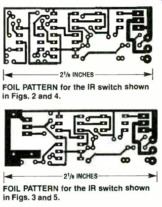
--- FOIL PATTERN for the IR switch shown in Figs. 2 and 4.
--- FOIL PATTERN for the IR switch shown in Figs. 3 and 5.
The time is determined by C5 and R4, and it can be varied to change the time delay of the timing cycle.
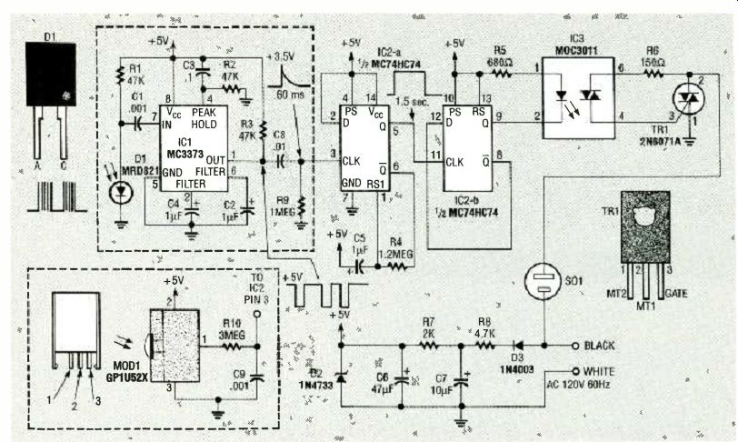
FIG. 1--THIS CIRCUIT WILL RESPOND TO ANY IR SIGNAL. Pulses are detected
by detector diode D1 and infrared amplifier /detector IC1.
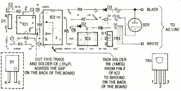
FIG. 2--PARTS-PLACEMENT DIAGRAM for the IR switch that contains D1
and IC1. TR1 must be placed with its metal side facing away from
board, and the side of the photodiode (D1) with the dot on it must
also face away from the board.
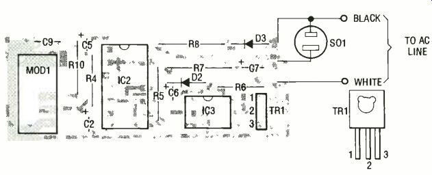
FIG. 3--PARTS PLACEMENT DIAGRAM for the IR switch that contains MOD1.
Use only the parts shown on this board, and disregard the parts that
are used only on the other board.
The time delay is necessary to convert the fast tone bursts from the transmitter into longer logic pulses that we can handle more easily. Once a signal is detected, IC2-a essentially latches on and remains low long enough for the incoming pulses to stop coming in. Once the cycle is over, IC2-a is again able to receive IR signals. That first pulse sets and resets flip-flop IC2-b, whose output (pin 9) powers the LED inside optocoupler IC3 (a Motorola MOC3011), which turns on the triac inside IC3. That turns on triac TR1, which supplies power to AC socket SO1 and the load.
When an IR signal is received once more, the Q output of IC2-b changes state, which disables the gate of TR1. Consequently, the next time the AC line voltage approaches zero, TR1 shuts off and so does the appliance plugged into SO1.
The IR detection circuitry IC1 and the components surrounding it, shown inside the dashed box-can be replaced by the GPIU52X IR module (MOD1), also shown in a dashed box. The Sharp GPIU52X module (also available from Radio Shack as catalog No. 276-137) is an IR detector circuit by itself.
You can use the parts that are easiest for you to get. Both circuits have a range of about 20 feet.
Assembly Each of the two IR detection circuits makes use of a different PC board, so we've provided the foil patterns for both. Figure 2 shows the parts-placement diagram for the board that contains IC1, and Fig. 3 shows the one containing MODI. The Parts List contains a listing of all parts for both boards-simply use only the parts shown on each board. Note that the PC board shown in Fig. 2 requires that a trace be cut and that two parts (C8 and R9) be tack-soldered to the back of the board.
-------------
PARTS LIST
All resistors are 1-watt. 5 %, unless otherwise noted.
R1-R347,000 ohms R4-1.2 megohms R5-680 ohms R6-150 ohms
R7-2000 ohms. 'i.2-watt R8-4700 ohms, 2 watts R9-1 megohm R10-3 megohms Capacitors Cl, C9-0.001 µF. ceramic C2. C4. 05-1 µF. tantalum electrolytic C3-0.1 µF, ceramic C6-47 µF, tantalum electrolytic C7-10 µF, 50 volts, electrolytic C8-0.01 µF, ceramic Semiconductors IC1MC3373 infrared amplifier detector (Motorola)
IC2MC74HC74 D-type flip-flop
IC3MOC3011 optocoupler (Motorola)
D1MRD821 infrared detector diode (Motorola)
D2-1N4733 5-volt Zener diode
D31N4003 diode
TR12N6071A triac
MOD1GP1U52X IR module (available from Radio Shack, part number 276-137)
Miscellaneous: PC board. heat-shrink tubing, wire, solder. etc.
Note: A kit for the infrared receiver (the one containing IC1) is available for $12.95 from DC Electronics, P.O. Box 3203, Scottsdale, AZ 85271-3203.
Call (800) 423-0070 or (602) 945-7736.
----------------------
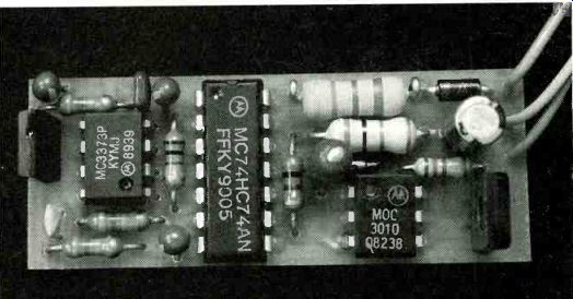
FIG. 4--FINISHED IR SWITCH. This one contains IC1 and D1: if those
parts are hard to find, you can build the one shown in Fig. 5.
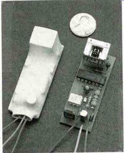
FIG. 5--THIS IR SWITCH uses an IR module instead of IC1 and D1.
It's shown here with and without heat-shrink tubing. The IR signal
passes right through the white heat-shrink tubing.
The procedures are detailed in Fig. 2.
When installing triac TRI, place it with its metal side facing away from board, and place the side of the photodiode (D1) with the dot on it so that is also faces away from the board-in other words, the dot must face the received signal.
The finished units are so compact that an enclosure is not necessary, although they should be properly insulated. A large-diameter piece of heat-shrink tubing can be used to enclose the entire board. That method permits the whole assembly to be placed inside an electrical switch box, an outlet box, or even a wall. The author's friend used double-sided tape to secure the units to overhead rail lamps throughout his house, making it very easy to turn the lights on and off by remote control. Figure 4 shows a finished board containing IC1, and Fig. 5 shows one with the IR module, with and without heat-shrink tubing. Note that the IR signal passes right through the white heat-shrink tubing.
Last word
To use the unit, point a TV or VCR remote control at the IR detector and push any button on the remote. Be sure to release the button immediately, otherwise you will turn off the appliance if you exceed the built-in delay of the receiver. You can use the "0" key by itself to avoid having your TV or VCR respond to the signal-or any other key if the "0" button has some specific function assigned to it.
A word of caution: If you ever have to service the appliance that's plugged into this device, be sure to unplug or disconnect the appliance from this device rather than just turning it off with the remote. The reason is because this circuit switches the neutral AC lead (white) rather than the "hot" lead (black). Because the circuit operates in that way, an AC voltage is always present inside a plugged-in appliance.
The number of applications for this circuit is virtually infinite. Aside from turning lights on and off, it can also turn older TV sets on and off. By connecting a relay to the output you can control just about anything.
R-E
Also see: WHAT'S NEWS