You can create unusual sound effects using some high technology with our voice changer.
by DAVID WILLIAMS
HOW WOULD YOU LIKE TO BUILD a device that will change your voice in real-time and let you sound like a completely different person? This remarkable circuit can shift a person's voice one octave higher or one octave lower in 16 graduated steps.
Just select the desired range and speak into the handheld microphone. You'll amaze your friends with the strange and hilarious voices that you can produce. The very lowest pitch makes your voice sound like a robot, and the very highest pitch makes you sound like a chipmunk! This project brings out the entertainer in everyone. Kids can put on puppet shows and use different voices to invent an endless number of characters.
Or, watch them take the microphone and imitate their favorite super-stars. They can even sing and create their own music videos if you have a camcorder! The voice changer is also fun over the telephone. You will be able to completely fool all of the people you call with your mysterious new voice or you can create amusing outgoing messages on your phone answering machine. No matter how you decide to use this exciting device, it is sure to give you and your family hours of non-stop fun and entertainment.
Circuitry to the schematic of voice changer shown in Fig. 1.
The voice-changer circuit performs real-time digital signal processing (DSP) of a person's speech. The main circuit consists of IC1, IC3, and IC4 which make up a 2-stage microphone preamplifier, a signal-processing unit and an audio power amplifier.
The user's voice is picked up by the electret microphone (MICI) and coupled to pin 2 of IC4-a, half of an LM358 dual opamp. Resistors R6 and R9 set the gain of IC4-a at approximately 8 (V_oUT = (R9/R6) x VIN). The output of IC4-a is AC-coupled to the input (pin 14) of IC1, an MSM6322 speech pitch control IC made by OK1. Figure 2 shows the internal function diagram of IC1 (the MSM6322). The input signal to pin 14 of IC1 passes through an amplifier with a gain of 10, which is set by external resistors RI and R5. The output of that amplifier passes through a 4th-order low-pass filter (LPFI) to an 8-bit analog-to-digital converter (ADC). The ADC samples the speech signal at 8.33 kHz under the control of the data processing unit, and the 8-bit digital values are stored in the internal 1kilobit RAM. Si the data processing unit clocks the RAM data into a digital-to-analog converter (DAC) that restores the analog signal. As long as the speech data is clocked in and out of the RAM at the same rate, the original signal is reproduced with no change in pitch-this is the normal default mode of operation when the voice changer is first turned on. By pressing the SCALE button S1, the output sampling rate is changed according to the values listed in Table 1.
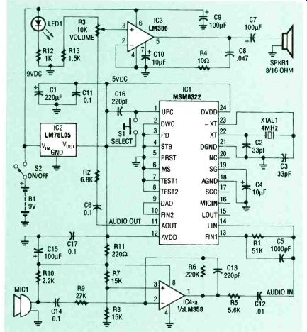
FIG. 1-VOICE CHANGER SCHEMATIC. The circuit performs real-time digital
signal processing of a person's speech.
-----------
FOIL PATTERN for the voice changer board.
As the DAC frequency is increased, the signal pitch is shifted higher. Conversely, the pitch is lowered as the sampling frequency drops. The result is analogous to speeding up or slowing down a tape recording during playback. The restored audio output from the DAC passes through a second low-pass filter (LPF2) and a buffer stage to the output (AoU , pin 11). The final amplification is provided by IC3, an LM386 audio power amplifier that drives the speaker (SPKR1). Capacitor C6 provides the AC coupling to IC3, and R3 controls volume.
---------------
PARTS LIST
All resistors are 1/4-watt, 5 %.
R1-51,000 ohms
R2-6800 ohms
R310,000 ohms, potentiometer with on /off switch (S2)
R4-10 ohms R5-5600 ohms R6220,000 ohms R7, R815,000 ohms R927,000 ohms R10-2200 ohms R11-220 ohms
R12-1000 ohms
R13-1500 ohms
Capacitors
C1-220-uF, 10 volts, electrolytic C2, C3-33 pF, ceramic C4, C10-10 uF, electrolytic C5-1000 pF, ceramic C6, C11, C14, C17 0.1 uF, ceramic C7, C9, C15-100 uF, electrolytic C8-0.047 RF, ceramic C12-0.01 µF, ceramic C13, C16-220 pF, ceramic
Semiconductors
IC1MSM6322 speech pitch control (OKI) IC2LM78L05 5-volt regulator IC3LM386N audio amplifier IC4LM358N dual op-amp Other components S1momentary pushbutton switch S2-on /off switch (part of potentiometer R3)
B1-9-volt battery MIC1 electret microphone SPKR1-8or 16-ohm speaker, 2.6 inches square Miscellaneous: PC board, UNIBOX #192 enclosure, 9 volt battery connector, IC sockets, knob for R3, wire, shielded microphone cable, hardware, solder, etc.
Note: The following items are available from LNS Technologies, 20993 Foothill Blvd, Suite 307R, Hayward, CA 94541-1511. 1-(800)-886-7150: MSM6322
Pitch Control IC (ICI)$15.00
Complete kit of parts for the voice changer, including PC board (with IC1 premounted & tested), enclosure, microphone, speaker, and all other components -- $59.00
Please add $5.00 shipping/handling.
California residents add local sales tax. COD, MC /VISA orders accepted.
-----------------
Assembly
The MSM6322 pitch control chip (IC1) is available from the manufacturer (OK1) only in a surface-mount package. The chip mounts directly to the foil side of the PC board (see the parts-placement diagram in Fig. 3. To properly solder ICI, be sure to use a soldering iron with a very small tip and be extremely careful to avoid solder bridges.
If you are not confident with soldering surface-mount devices, you can purchase the kit mentioned in the Parts List: in this kit. IC1 comes pre-soldered to the circuit board and has been tested.
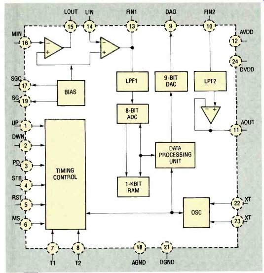
FIG. 2--INTERNAL DIAGRAM OF IC1. The input signal is amplified and
then passed through a 4th-order low-pass filter to an 8-bit analog–to-digital
converter which samples the speech signal at 8.33 kHz. The 8-bit digital
values are stored in the internal 1-kbit RAM.
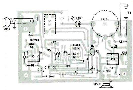
FIG. 3--PARTS PLACEMENT DIAGRAM. IC1 is available only in a surface-mount
package. The chip mounts on the foil side of the PC board. If
you purchase the kit mentioned in the Parts List, IC1 comes pre-soldered
to the circuit board. LED1, S1, and R3 also mount on the foil side
to allow the parts to fit through the top of the enclosure.
Pay careful attention to the mounting holes on the PC board before you solder the ceramic capacitors. Because capacitors vary in size, the locations for C6, C12, and C14 have three holes to accept either large or small sizes.
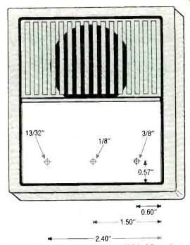
FIG. 4--DRILL THE THREE HOLES in the top cover for LED1, S1, and R3
as shown here.
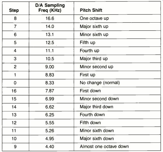
TABLE 1 PITCH CONVERSION TABLE
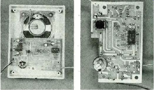
FIG. 5--THE INSIDE OF THE COMPLETED UNIT. Everything fits nicely inside
the case, shown on the left. IC1 comes premounted on the solder side
of the board (right).
The next three components (LED1, S1, and R3) are mounted on the foil side of the circuit board along with IC1. That allows the parts to fit through the top cover of the plastic enclosure. When soldering the LED in place, make sure that the bottom edge of the LED is ¼-inch away from the board. Potentiometer R3 has on /off switch S2 built-in: the PC board has a special cutout to allow clearance of the switch mechanism. When the part is properly positioned, the five metal soldering rings will line-up with the corresponding pads on the PC board. After R3 has been soldered in place, you must remove the small metal tab sticking straight up from the edge.
Strip about 1/2 inch of the outer insulation from the ends of a piece of shielded coaxial cable, and then strip about 1/8 inch from the center conductor on both ends. Tin all loose ends of the cable. On the back of the electret microphone you will see that one of its two leads is directly connected to its metal case; this is the ground lead.
Solder one of the coaxial cable's shield (outer) leads to the ground lead of the microphone.
Then solder the center conductor to the other lead of the microphone. Insulate any exposed microphone leads with heat-shrink tubing or RTV silicone.
Connect the microphone wires into the PC board as shown in Fig. 3. Now remove IC3 and IC4 from the protective foam and install each into its appropriate socket. Cut two pieces of insulated wire about 5 inches long and strip 1/4 inch from all ends. Solder a wire to each terminal of the speaker and then to the PC board. Finally, attach the wires for the battery connector.
If you use the enclosure included in the kit, drill the three holes in the top cover as shown in Fig. 4. Then place the speaker over the 4 plastic pegs in the case and secure it in place. Next, remove the nut and washer from the potentiometer R3, and position the PC board so that S1, LED1, and 52/R3 protrude through the holes drilled in the case. The PC board should lie flat against the four plastic standoffs. If the board won't lie flat, check to make sure that you have removed the small metal tab from the potentiometer. Secure the PC board in place with four No. 4 x 1/4-inch self-tapping screws.
Turn the case over and thread the washer and large nut back onto R3 to securely anchor everything in place. Slide the plastic knob onto the shaft of R3 and tighten the setscrew to hold it firmly in place. Cut or file a slot in the edge of the case for the microphone cable in so that it won't be pinched when you put the case together. Figure 5 shows the completed unit.
Operation Install a 9-volt battery, turn the unit on, and set the volume control about halfway. The LED should light to show that the unit is receiving power. Keep the microphone away from the speaker or you will experience a loud feedback squeal. Each time the voice changer is turned on, it powers up in the normal mode, where there's no pitch change. If you speak into the microphone at this point, you should hear your normal voice from the speaker.
Each time you press switch S1, the pitch should rise one step. After 8 presses, the voice changer will be operating at the maximum high pitch shift (one full octave higher). On the 9th press of S1, the circuit should jump to the maximum low pitch shift (one octave down). The next 8 presses of Si will cause the pitch to rise and finally re-turn back to normal. The individual pitch change steps are shown in Table 1.
If your unit is working properly, you should experiment to see how your voice sounds at each of the steps. Also, you can bring the microphone near the speaker to produce feedback deliberately. The feedback in the normal mode is merely an annoying squeal, but with some of the pitch shifts, you will hear some interesting effects that sound like a spaceship or a ray-gun.
-R-E
Also see: Boot Your PC Remotely