A PLL circuit will help us generate missing horizontal sync pulses.
Once upon a time, when gated sync was the last word in video signal scrambling, it was relatively easy to de- scramble the system there were two constants you could count on.
The first was that the missing horizontal sync pulses were recoverable from information that was buried elsewhere in the RF signal. The second, more subtle, constant was that the horizontal sync pulses were always missing from each line of video.
The SSAVI system makes this part of the descrambling process a bit more difficult.
As we've discussed over the last couple of months, the horizontal sync pulse in the SSAVI system is considerably sneakier than in any previous scrambling technique. In any given field of video, the pulses can be absent or at the wrong levels. They could be present, although the chances of that are small. The only constant is that the horizontal pulses will be there during the vertical interval -and that's while the electron beam is off the screen.
Given all that, the job us is to come up with some way to generate horizontal pulses only when they're needed. Not only that, but we have to be sure that the pulses we create are placed correctly on each line, and are produced at the exact same rate as the horizontal frequency of the incoming scrambled video signal. This sounds like an insurmountable design problem but, in fact, it's not really that difficult. The key to the design is the use of a phase locked loop, or PLL. The phase -locked is one of the most useful subcircuits, and one of the most underused as well. Back in prehistory, when dinosaurs roamed the earth and the IC hadn't been invented, the design of phase -locked loops was a real pain in the neck.
They were complete circuits in themselves, and several people were usually required to complete the designs. That changed completely with the introduction of IC's in general, and the CMOS family in particular.
Before we get into the details of how a phase-locked loop circuit is going to solve our sync problem, it's worth spending a few minutes on the basics of phase-locked loops.
Since this is such an important part of our total circuit, it's impossible to understand how the descrambler works without a foundation in the theory of phase-locked loops.
The basic components of a standard phase -locked loop are shown in Fig. 1. There are two basic parts: the first is an input conditioning circuit that cleans up the signal applied to the phase detector, and the second is a local oscillator whose frequency is determined by a control voltage. That part is usually referred to as a voltage -controlled oscillator (VCO) or voltage-to-frequency converter.
The output of the VCO is compared to the input frequency, and the phase detector generates an error voltage that's proportional to the difference between the two frequencies. The error voltage controls the frequency of the VCO, and the result is that the VCO's output is always in-phase -or synchronized, if you prefer that term -with the input frequency.
By setting the VCO's base frequency to some multiple of the input frequency, we can have the counter /divider chop the VCO frequency down to the input frequency and keep the VCO in sync with the input, even though the frequencies aren't the same. So, PLL's let us easily multiply frequencies, build filters, and -more to our point -keep signals in sync.
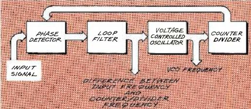
FIG. 1--PHASE -LOCKED LOOP BLOCK DIAGRAM. The two basic parts of a phase
locked loop are the input conditioning circuit and the voltage-controlled
oscillator.
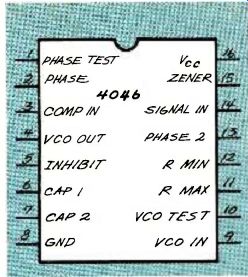
FIG. 2--PINOUT DIAGRAM for the tried-and-true 4046 PLL.
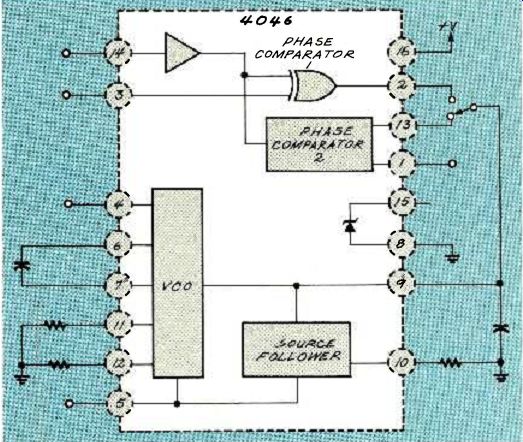
FIG. 3--4046 BLOCK DIAGRAM. The frequency of the VCO is determined by the
resistors at pins 11 and 12, the capacitor between pins 6 and 7, and the
control voltage on pin 9.
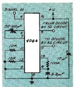
FIG. 4--4046 PLL SETUP. The VCO base frequency is set at 504 kHz, which
is the horizontal scan rate (15750 Hz) multiplied by 32.
Phase -locked loops are basic building blocks in circuit design, and it's well worth your time to learn as much as possible about them. I might spend more time on them in the future, but at the moment my only interest is how they can be used in descramblers. I strongly urge all of you out there to read about, experiment with, and build PLL circuits. There's a lot of good information around regarding phase-locked loops and a good deal of it comes from the semiconductor manufacturers themselves. I know that Signetics has a whole data book devoted to phase -locked loops. Give them a call (408-991-2000) and find out how you can get a copy of their "Phase Locked Loop Handbook." While it's not really the kind of reading that will keep you up at night, it's a very good source of information.
The phase-locked loop we'll be using is the old tried-and-true 4046.
The pinout for the chip is shown in Fig. 2, and a block diagram of the chip is shown in Fig. 3. The frequency of the VCO is determined by RC constant of the resistors at pins 11 and 12, and the capacitor between pins 6 and 7. A second factor affecting the VCO is the control, or error voltage on pin 9.
The VCO will stay in sync with the input frequency that's applied to pin 14. If you put a divider circuit between the VCO output on pin 4 and the comparator input on pin 3, the VCO frequency will be the input frequency multiplied by whatever value you're using for the division.
There are lots of things to watch out for when you're designing a circuit around a 4046, or any PLL for that matter, but we're more interested in the application than the theory. I'll leave the theory for another column--and by that time you'll have gotten the data books and learned a lot about phase-locked loop theory on your own. Right? In our descrambler, the PLL is the perfect solution for solving the horizontal sync problem. Remember that the only time we can be sure of receiving transmitted sync pulses is during the vertical-blanking interval.
The question we had to answer is how any circuit could "know" when to generate a horizontal sync pulse if there's nothing that can be used as a reference. The way to make that happen is to do a couple of creative things with a PLL. To start off with, the 4046 setup we need is shown in Fig. 4.
The VCO base frequency is set at 504 kHz. That frequency is an even multiple of the standard horizontal scan rate (15,750 Hz x 32). During the vertical interval, we get 26 usable horizontal sync pulses from the broadcast signal. When line 27 comes along, the picture starts and the horizontal sync is missing. But because the VCO is still running, the divider produces a horizontal sync signal anyway. The pulse is fed back to the input video amplifier and injected into the video signal so that line 27 is displayed correctly on the TV. The artificially generated sync signal is then split from the video signal by the sync-separator circuit and routed to the PLL. The 4046 has no way of knowing that the sync pulse isn't a "real" one, so it treats it exactly the same as one obtained from the television broadcaster.
This kind of self-bootstrap operation continues for the rest of the video frame until the next vertical interval is reached, when the whole thing starts all over again.
As you can see, the success of this whole scheme depends completely on the stability of the VCO in the phase-locked loop. In fact, while that might seem to be a real concern, it's really much less of a problem than you might think. I'm not going to go into the math, but your TV has a tremendous amount of tolerance, and even a ten percent drift in the VCO frequency won't cause much in the way of noticeable shakiness in the TV picture.
Get the phase-locked loop circuit working and closely examine the horizontal sync pulses on your scope. The demo scrambler we built some time ago is the perfect circuit to shut off the transmitted horizontal sync signals periodically.
Do that and then watch the results on the oscilloscope.
------------------
Also see: