by JAMES MELTON
Stop wasting power-turn off your appliances automatically with an electronic time-delay relay.
OUR TIME-DELAY RELAY WILL DRIVE up to a 3-ampere AC load for a specified period of time, and then shut the load off automatically. It can turn electrical appliances and lights off after a time interval ranging from just a few seconds all the way up to about an hour.
One of the many possible jobs for the relay is the control of indoor Christmas lights just push a button and the lights will stay on for a few hours, and then automatically turn off.
Outdoor Christmas lights, although a considerably larger load, can also be controlled by one of these relays.
The author has several different antennas that are connected to amateur radio equipment in his garage. As a precaution, the feedlines to the radios are routed through mechanical relays that keep them grounded when not powered, and they are connected to the radios only when the reset switch on the time-delay relay is pushed. Several hours later, if he has been called away from the radios (and forgotten that they were on), the relay drops out, and the antennas will have been automatically grounded.
One of these units can even be used with a coffee maker. Quite often coffee makers are left on overnight or over the weekend; the owner returns to find a ruined coffee pot-and a very hot one at that. A time-delay relay in the burner circuit will solve that problem. Simply set the timer to stay on for 2 hours, and if it's not reset, it will allow the coffee pot to cool off.
Operation
The circuit, shown in Fig. 1, is based on a 4060 CMOS 14stage binary counter with an on-board oscillator driver. The basic frequency is set by the values of R1, R2, and C1 and it's roughly 1 /R1 x C1. Resistor R2 should be about 10 times the value of R1. The values shown generate an approximate 4.5hertz frequency, which is then divided down by IC1. Divided outputs are available ranging from divide-by-4 to divide-by-16384 (see Fig. 1). The chosen output is tied to the base of Q1 through current-limiting resistor R4, and to the base of Q2 through R3. Transistor Q1 is the hold transistor for the timing circuit, and transistor Q2 turns on the solid-state relay.
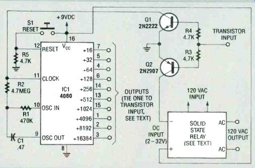
FIG. 1-THE CIRCUIT is based on a 4060 CMOS 14-stage binary counter
that controls a solid-state relay.
When you push reset button S1, all of IC1's outputs go low (including the one you have tied to the transistor input). Transistor Q1, an NPN unit, shuts off and its collector, which is tied to timing resistor R2, presents no load to the timing circuit. Transistor Q2, a PNP unit, turns on when a low is applied to its base, thus turning on the solid-state relay.
When the chosen output of IC1 goes high, Q1 turns on, grounding the clock input to IC1, stopping any further counting until Si is pushed again. At the same time, Q2 shuts off, which turns off the solid-state relay, thus cutting off power to the load.
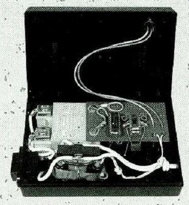
FIG. 2--THE PROTOTYPE RELAY is built on a small piece of perforated
construction board mounted on the end of the solid-state relay.
Construction
The author built his prototype relay on a small piece of perforated construction board using point-to-point wiring, and arranged the parts so that the board would mount on the end of the solid state relay (the input terminals are big enough to support the circuit board). Figure 2 shows the inside of the prototype. Note that the author has built in a 9-volt power supply that is not shown in the schematic.
PARTS LIST
All resistors are 1/4-watt, 5 %.
R1 470,000 ohms
R2 - 4.7 megohms
R3, R5-4700 ohms
Capacitors C1--0.47 µF, 25 volts, tantalum
Semiconductors
IC1-4040 CMOS timer /divider
Q12 N2222 NPN transistor
Q22 N2907 PNP transistor
S1 Normally-open pushbutton switch
Miscellaneous: Solid-state relay (sized for the application you have in mind), perforated construction board, wire, solder, AC linecord, project case.
The relay in action To use the solid state relay, simply plug the relay into a 120-volt outlet, plug an appliance (that draws no more than 3 amperes) into the time-delay relay, and push the reset button. The circuit will begin timing and will shut off at the end of the period you have selected. When you use the time-delay relay to shut off your appliances, you'll not only be adding a safety feature and saving money you'll also be doing something good for the environment!
Also see: