
Real-world considerations.
by ROBERT GROSSBLATT
Before we close this subject (for the time being at least), you all should be aware that the SSAVI system is several years old and has undergone some changes. The basic principles are the same, and the circuitry we've developed is the way to go if you want to descramble it, but the chances of building our design, hooking it up to your TV, and seeing an unscrambled picture, are about the same as finding any intelligent life on Pluto.
The two most significant changes in the SSAVI system involve horizontal sync and picture inversion.
The first is no problem, but getting around the second one is going to take a bit of brain activity on your part.
In the original SSAVI system, horizontal sync was never inverted during active video (when the picture was showing up on the TV), but that has changed. The video waveform in Fig. 1-a shows the state of the horizontal interval as of fifteen minutes ago (as of this writing) on my cable. I've drawn it with an unscrambled horizontal interval so you can see how the scrambled signal relates in time to the normal one in Fig. 1-b. A change has been made to the 4.7 microsecond position normally occupied by the horizontal sync signal. There are also two 1 microsecond spikes at the very beginning and end of the horizontal interval. If you watch a scrambled picture, you can see these at both ends of the interval as it weaves its way down the middle of your screen.
These spikes peak at 100 IRE units but since they're not really in the horizontal interval, they don't cause any problem. If I had to make a guess as to why the "woop-dee-doo" has been added to the horizontal interval, I'd say that it's to keep people from doing what we're doing--adding a single sync pulse to restore the signal.
When I was designing the section of the descrambler that put the horizontal sync pulse back in the interval, I had to modify the circuit slightly to make it work. Basically, all I did was add some gates to the output of the 4040 line counter to create a pulse that started 2 microseconds into the horizontal interval and had a width of 4 microseconds--the approximate length of the horizontal sync pulse. I used it to gate the incoming video, completely eliminate the change from the transmitted signal, and make sure that the only thing that appeared in that section of the line was the generated horizontal sync from the phase-locked loop.
During the vertical interval, of course, this entire activity was disabled to allow the transmitted sync (which is still being sent in the clear) to be passed through the descrambler.
The polarity indicator for the picture still works as I described, but the newer SSAVI systems (at least the one in my area) move it around between lines 20 and 22. This is actually a dangerous thing for cable companies to do, since line 22 is usually considered to be active video.
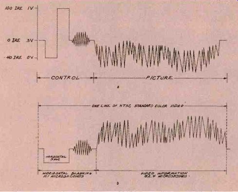
FIG. 1--This video waveform shows one variation on the SSAVI system.
A change has been made to the 4.7-microsecond position normally
occupied by the horizontal sync signal, and there are 1microsecond
spikes at the beginning and end of the horizontal interval.
The information as to where it will be is probably buried in the subscriber codes, which are difficult to decode. The code format is usually as a series of 32-bit words with bits that are about 2-microseconds wide at a data rate of 504 kHz (which should be a somewhat familiar number).
How to handle this problem depends on the nature of the scrambled signal in your area. You can decode the marketing code and figure out which bits indicate the correct line to examine for determining the polarity of the following video frame, but that is an involved subject and there's just not enough room here to go into it. It's also not the best approach since there's nothing stopping the cable companies from putting the code somewhere else or, to make matters even worse, change the encoding algorithm.
A second way to deal with the problem is to examine the vertical interval on a scope, see where the polarity indicating lines are, and work out some circuitry that examines them all. Remember that what has changed is the location of the line (it now moves around from place to place), and not the structure of the line. In essence, if there are three lines to examine, a high in the second half of any of them would indicate that the next video frame is inverted. That's the approach I took.
One interesting piece of information I can pass along to you is that, again in my area only, the video is always inverted. Check the signal in your area and see if that's true for you as well. If it is, the design of the descrambler is much simpler.
Before you get to work, however, some thought has to be given to the things that might be done in the future. Since the SSAVI system has changed over the years, there's no guarantee that the way you go about detecting inverted video today is going to hold up tomorrow.
Put yourself in the shoes of a cable company executive and look at the problem from his point of view.
You're spending a lot of money for the cable boxes and, while the fundamental scrambling method can't change (it's built into the basic circuitry of the box), the hooks and signals that tell the box what to do can certainly be moved around the vertical interval. If I were designing their system, I'd put a bunch of alternate encoding methods in the EPROM. They would include the ability to store the inverted-video indicator directly in the marketing codes as well as being able to change the format of the codes themselves.
If you go through the trouble of building something to detect the state of video by looking at line 20, it can all be made useless if the cable company moves the information somewhere else. Restoring horizontal sync is pretty much locked in stone, but I can definitely think of a few ways that even that could be changed.
Remember that large-capacity EPROM's are cheap, and there's nothing stopping the cable company from putting several encoding techniques in the chip. To guarantee your work against obsolescence, the techniques you use to clear up inverted video have to depend on things that can't be easily changed by the cable company.
There's a much more interesting way to deal with the problem. I haven't worked out the circuitry yet, but I'll pass it along for all of you to kick around.
The vertical interval provides a lot of information. One thing we haven't talked much about is the white and black levels. I don't bother too much with these because the TV (or VCR) has excellent circuits to clamp the levels and condition the video signal before it reaches the sync separator. I've found that if I feed the video in at anywhere from 1.2 to 1.5 volts DC, the TV or VCR doesn't have any trouble working out the levels for itself.
The black level (0 IRE) should be about 0.3 volt and the white level (100 IRE) should be about 1 volt.
Super black is the bottom of sync (40 IRE) and is at 0 volts. Even if you can't find the polarity line to get the white level, you can always get the black and super-black levels from the unscrambled transmitted sync that's sent in the vertical interval. You can even get the black level of the video signal in the horizontal intervals during active video from the 5microsecond section containing the back porch.
Once you know the black level, you can integrate the picture part of the line to get the average DC voltage of the signal. That's the same sort of thing we had to do to isolate vertical sync from the composite sync signal. If it's below the black level, you know that the line has been inverted, and if it's higher, then you know that the line was normal.
You'll probably have to filter out the chroma and look at the luminance (DC level) of the line, or else the circuit might have a hard time telling the difference between a dark normal video line and a bright inverted line.
If you do that, one other clue that will help detect an inverted line is that the picture's DC level should never get below about 20 IRE. If it does, the TV's vertical sync detector might sense it and falsely trigger a vertical retrace. That's the sort of thing that frequently happens when you try to view a scrambled video signal--even if the transmitted signal isn't doing anything to the original vertical interval.
Since video is inverted (or not) by the cable companies on a frame–by-frame basis, it's safe to assume that finding an inverted line means that the next one will be inverted as well.
Remember that the descrambler is completely reset during the vertical interval when vertical sync is detected.
There's no way that I can provide you with an absolute method to descramble the video in your area-there are just too many subtle variations that can be added to the basic SSAVI system. The ones I just described are only a few of the many possible twists that can be done to a video signal.
The approach and circuitry we developed over the last few months-as well as the theory--should give you a good head start for working out the details that have to be added to deal with the particular scrambling method used by your cable company.
Here's an offer. If you've been following this topic, have been designing a circuit that will work in your area, and are having a problem, drop me a note and I'll help you out. The more information you give me, the more help I'll be able to give you. At a minimum, what I want to see from you are schematics, block diagrams, concise descriptions of the problem you're having, and I'd like either scope photos or drawings of the video signal.
Also see: Link | --COMPUTER CONNECTIONS