By DAVID J. SWEENEY
Avoid potential road hazards, as well as potential embarrassment, with the Smart Turn Signal.
EVERYONE WHO DRIVES A CAR occasionally forgets to shut off the turn signal. That sends the wrong message to other vehicles and could cause an accident. At the very least, other drivers will assume that there's an idiot at the wheel of a car whose turn signal continues flashing long after the turn has been made.
An electronic turn-signal alert, able to remind the driver that his turn signal is continuing to flash, could prevent an accident or at least save the driver some embarrassment.
We have a circuit that is sure to be welcomed by drivers worldwide. It sounds a warning signal whenever a blinker has been left on for more than 15 seconds. If, however, a blinker is left on while the driver is waiting to make a turn, that warning signal would become more annoying than helpful. In that case the Smart Turn Signal remains silent. Also, when the warning signal sounds, it starts off softly, and then gets louder, in the event that road noise prevents the driver from hearing the alarm.
The Smart Run Signal, or STS, is easy to install in any car because it connects only to the contacts on a typical auto-motive flasher and to the brake-pedal switch-one need not interfere with the car's wiring.
A typical flasher Figure 1 shows a representative schematic for a typical automotive flasher. When you operate the turn signal, the heating element and 50-ohm resistance wire are connected in series with the turn-signal lamps. With a 50-ohms resistor in series, the lamps will not light. As current passes through the heater element it warms up, heating the bimetallic contacts which then close (the clicks you normally hear from a flasher), bypassing the resistance wire and heater.
That's when the turn signal lamps are lit. The bypassed heater element then cools, allowing the bimetallic contacts to open, reconnecting the heater and resistor wire in series with the bulbs. The process repeats as long as the flasher remains connected in the circuit through the driver's turn-signal control switch. To add delayed, dynamically varying sound to the turn signals, you can add the Smart Torn Signal circuit a standard flasher circuit.
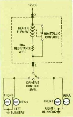
FIG. 1--A TYPICAL AUTOMOTIVE flasher. Initially the heating element
and a 50-ohm resistance wire are in series with the turn signal lamps
so they do not light. When the heater element warms up, the bimetallic
contacts close and bypass the resistance wire and heater, allowing the
lamps to light. The bypassed heater element then cools. allowing the
bimetallic contacts to open.
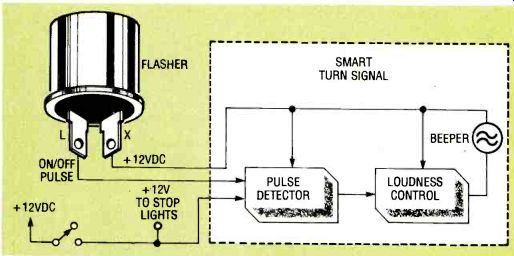
FIG. 2--Flasher terminal L connects to the load and X connects to the
12-volt supply.
When the driver engages the turn signal, the L terminal voltage varies with the blinking lights. The STS senses the changing voltage and, after 15 seconds, it applies power to a buzzer through a current-limiting device to control loudness.
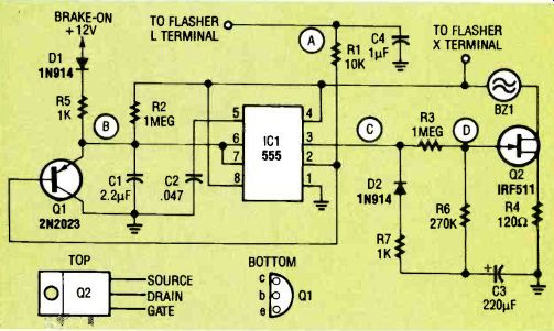
FIG. 3--STS SCHEMATIC. The Q2 gate voltage increases with the charge
on C3. After 15 seconds of charging, the buzzer will warble. As the charging
continues, the sound will grow louder.
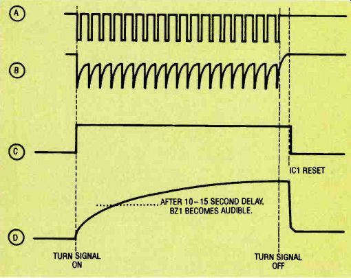
FIG. 4--CIRCUIT WAVEFORMS. Point A shows the signal from the flasher.
The voltage at point D will increase as long as the pin-3 output of IC1
(point C) remains high. The C1-R2 time constant (point B) determines
how long the output will be high.
Figure 2 shows how the STS and flasher work together.
Flasher connections are usually labeled L and X, where L connects to the load and X connects to the vehicle's 12-volt supply.
The L connection remains at 12 volts until the driver engages the turn signal. The voltage then varies with the blinking lights. The STS senses that changing voltage, unless the brake is applied, and applies power to a buzzer through a current-limiting device to control loudness. The buzzer's loudness varies with current.
Circuit operation Figure 3 is the schematic diagram for the STS. In order for the buzzer (BZ1) to sound, Q2 must be turned on. As the voltage at point D (Q2's gate) increases, the current through BZ1 increases, with a resulting increase in loudness. The Q2 gate voltage increases with the charge on C3. To charge C3, pin 3 of IC1, a 555 timer, switches from low to high when the first pulse from the turn signal is applied to pin 2 of IC1. With the values shown for R3 and R6, the initial voltage at Q2's gate will be nearly sufficient to sound the buzzer. After C3 charges for 15 seconds, the voltage will be high enough for the buzzer to warble and, as the charging continues, the sound will grow louder.
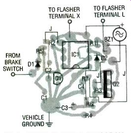
FIG. 5--PARTS-PLACEMENT DIAGRAM. You must make your own circuit board
if you want to use one, as they are not for sale. Otherwise use perforated
construction board.
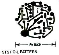
----------STS FOIL PATTERN.
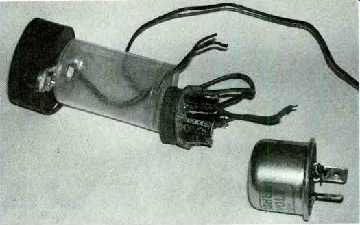
FIG. 6--YOU CAN PACKAGE THE UNIT in a 35 mm film canister which takes
advantage of the size and shape of standard turn-signal flashers, as
well as the STS PC board.
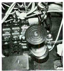
FIG. 7--THE STS FLASHER plugs into the original flasher socket.
Figure 4 shows some of the waveforms at various points in the circuit. Notice that the voltage at point D continues to increase as long as the pin-3 output of IC1 remains high.
When the output goes low, C3 rapidly discharges through D2.
The 555 timer (IC1) operates as a one-shot multivibrator, where a negative going input to pin 2 causes pin 3 to go high, until C1 charges through R2. The C1-R2 time constant determines how long the output would be high, and is set to about 2 seconds with the values shown. lb keep the 555 output high, transistor Q1 operates as a missing-pulse detector (see Electronics Now, November, 1992). While the first negative pulse from the flasher sets pin 3 of ICI high, later pulses turn on Q1, which shorts C1 and restarts the charging cycle. As long as the turn signal operates, the pulses continue to keep C1 discharged and pin 3 high.
When the driver's foot is on the brake pedal, 12 volts is applied to the anode of D1. Capacitor C1 then quickly charges through R5, resetting IC1 after every turn signal pulse, and the buzzer does not sound.
----------------
PARTS LIST
All resistors are 1/4-watt, 5%.
R1-10,000 ohms
R2, R3--1 megohm
R4-120 ohms
R5, R7-1000 ohms
R6 270,000 ohms
Capacitors
C1-2.2 µF, electrolytic
C2-0.047 µF
C3-220 F, electrolytic
C4-1 µF, electrolytic
Semiconductors
IC1-555 timer
D1, D2-1N914 diode
Q12N2023 PNP transistor
Q2IRF5'1 FET
Other components
BZ1 Piezoelectric buzzer (Radio Shack RS273-066 or equivalent)
Miscellaneous: PC board, turn-signal flasher, 35 mm film canister or other suitable case, wire, solder.
------------------
Packaging
The STS circuit can be assembled on one small PC board. We've provided the foil pattern in case you want to make your own. See the parts-placement diagram in Fig. 5. All parts are mounted vertically on the board. Also note that a few jumpers, marked "J," must also be installed on the component side of the circuit board; use insulated wire for the jumpers to avoid any possible shorting on the small board.
Because this project will be operating in your motor vehicle, extreme care should be taken to produce a reliable, quality device. A failure could result in annoying beeping or in a short circuit to the turn-signal flasher. To package the unit, use a solid, weather-tight case, such as the 35 mm film canister shown in Fig. 6. The cylindrical packaging takes advantage of the size and shape of standard turn signal flashers, which fit snugly in plastic 35 mm canisters. The STS PC board is also circular, and sized to fit inside a film canister. The buzzer is mounted on the base of the film can.
Drill the holes in the film can for the wires. Make all connections to the flasher directly to the prongs, as close to the body of the flasher as possible. A separate ground wire will be necessary. If your car has a three-prong flasher, one prong will provide a ground connection.
It should take only a few minutes to install the STS flasher in your car. It plugs into the original flasher socket as shown in Fig. 7. If the STS fails to work when installed, switch the wires connected to the flasher prongs.
If, when you go to install the smart turn signal in your car, you find that it's too tight under your dashboard to fit the entire unit as one assembly, simply run leads to the flasher terminals and mount the rest of the unit wherever you find room.
Just make sure the circuit is well protected and mounted where it won't interfere with anything else.
Also see: