Build this low-cost, 50-ohm amateur radio dummy antenna; it can dissipate 100 watts in the 160 to 10 meter bands.
By LINTON G. ROBERTSON
THE DUMMY ANTENNA OR DUMMY load described here will substitute for "the real thing" when you want to tune or test a transmitter "off-the-air" and prevent the radiation of interference.
This 50-ohm load will dissipate up to 100 watts in the 160- to 10-meter amateur bands.
The term "dummy" as in dummy antenna has its origins in the word "dumb," a belittling term for a person unable to talk. However, it evolved into the word dummy, which means an imitation or substitute for the real thing, as in a ventriloquist's large puppet. In radio frequency practice, it is a kind of "black hole" for incoming radio signals; the energy goes in, but never comes back out again.
What is a dummy antenna? It is really a resistor (or group of resistors) matched to the characteristic impedance of the feed line, and it has a power-dissipation rating at least as great as the transmitter's output power. An important requirement is that it have no inductive component which could make it frequency-sensitive. It should provide a voltage standing wave ratio (VSWR) as close as possible to 1.0. A dummy antenna can also be a useful tool for testing receivers for internally generated noise.
This test can be performed when the receiver is effectively shielded from any external interference that could enter its antenna terminals. These tests are usually carried out in metal-screened enclosures called, appropriately enough, screen rooms.
The design of a dummy antenna design will depend on the transmitter's operating frequency and power. For low-power citizen band or marine-band radio transmitters, the dummy antenna is typically a small, machined cylinder that includes both a coaxial cable receptacle and resistor. The feed-cable plug is disconnected from the antenna and plugged into the load receptacle. A factory made unit of this kind could cost up to $50. At microwave frequencies, a dummy antenna can be a waveguide section that includes graphite sand which acts as the resistor. If transmitter output power is to be determined, the waveguide section will include a water load that acts as a calorimeter. Power dissipation can be calculated from the increase in water temperature.
Build your own
One way to learn more about dummy antennas-and at the same time save money-is to make your own. The dummy antenna described here is easy to make from low-cost, readily available parts, and you can save a few dollars over the price of even the lowest cost store-bought unit.
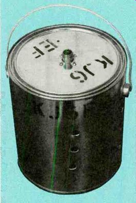
To build this dummy antenna, you will need eight 100-ohm, 3-watt carbon resistors, an SO-239 UHF coaxial panel receptacle, a one-gallon paint can, and some brass strips. The resistors and receptacle can be obtained from mail-order houses or most electronics stores, and the new, clean gallon container can be obtained from a paint store. (They are stocked for custom-mixed paint.) Figure 1 is a cutaway view of the completed dummy antenna.
Note that the resistors are arranged in a series-parallel network formed by soldering them to parallel strips of sheet brass.
The strips are 1/8-inch wide, 20- to 30-gauge sheet brass, obtainable precut in lengths of two feet or more from many building supply and hardware stores.
The flat strip form reduces possible effective inductance, and brass is stiffer than copper of comparable thickness. It also has a lower resistance than iron or steel.
If molded carbon composition units are not available, carbon thick-film resistors can be substituted. The calculated effective value of the network is 50 ohms, slightly less than the 52-ohm characteristic of the feed line. However, if one considers the tolerances of actual resistors, a measured value would not be precisely 50 ohms.
Nevertheless, if the network is built as specified here, the effect on VSWR should be negligible.
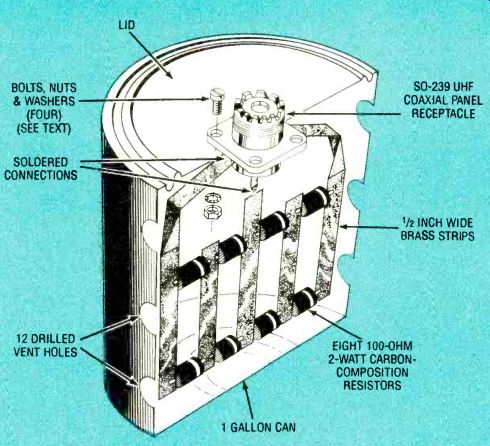
FIG. 1-Brass strips form a low-resistance bus for the series-parallel resistor
network. The one-gallon can protects against burns and electric shock.
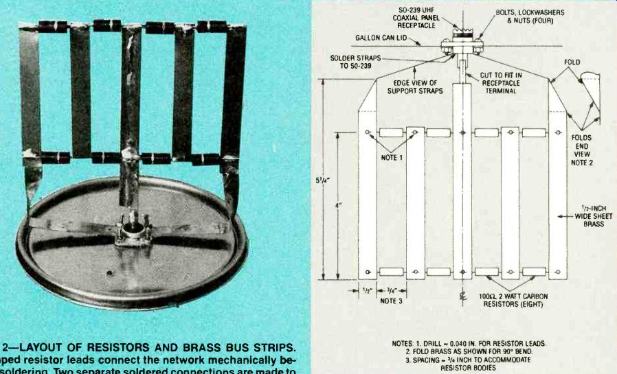
FIG. 2 LAYOUT OF RESISTORS AND BRASS BUS STRIPS. Crimped resistor leads
connect the network mechanically before soldering. Two separate soldered
connections are made to the SO-239 receptacle.
NOTES:
1. DRILL-0.040 IN. FOR RESISTOR LEADS.
2. FOLD BRASS AS SHOWN FOR 90° BEND.
3. SPACING-1/4 INCH TO ACCOMMODATE RESISTOR BODIES
Assembling the network
Refer to Fig. 2, the resistor and bus layout drawing. and start construction by cutting one strip 15 inches long for supporting the network from the shell of the receptacle. Cut a semicircular notch about I /4inch deep by 3/8-inch wide at the middle of the strip to provide clearance around the coaxial terminal at the back end of the SO-239 receptacle. This will still provide an adequate surface for soldering the completed network to the end of the receptacle's shell, later in the project.
Then cut another strip about 6 inches long and cut a narrow tongue at one end that can be press-fit into coaxial sleeve at the receptacle's end. Next cut two more strips 4 inches long.
Drill the ten 0.040-inch holes in the brass strips in the locations shown in Fig. 2 for inserting and crimping the resistors later in the project. Clean the brass strips thoroughly with steel wool or abrasive cleaning powder and water to remove surface oxidation, oil, or grease. Wash and dry the strips.
Fold the ends of the 15-inch strip as shown in Figs. 1 and 2 so that the central section will be bent 90° away from the vertical ends where the resistors are to be soldered.
The next step is to bend and insert the axial leads of the resistors in the drilled holes and crimp them to link the network together mechanically before doing any soldering. Lay out the brass strips as shown in Fig. 2, and position the ten resistors between the strips. With pliers, bend the leads 90° so that they can be inserted into the holes drilled in adjacent strips, allowing room for the resistors to fit between the edges of the strips.
Insert the resistor leads, trim their ends, and fold them back on themselves. Then crimp them flat against the brass strips. Set the mechanically "linked" network aside.
Prepare the container
Drill a 3/8-inch hole in the center of the can lid by first drilling a pilot hole with a small drill or center drill. With a round file, carefully enlarge the 3/8-inch hole until the SO-239 jack is admitted snugly. With a felt tip pen, mark the centers of the four holes on the receptacle's panel-mounting plate on the lid top. Punch the centers with a nail or nail set, and drill them for the four 10-32 bolts.
Position the receptacle on the outside of the lid, and fasten it with four 1/4-inch long 10-32 bolts, lockwashers, and nuts.
Drill 12 ventilation holes with the 3/8-inch drill in four vertical columns of three, 90° apart as shown in Fig. 1. Start first with pilot holes as previously described. The can will isolate the hot resistors from contact with your hands and prevent any fire or shock hazard when the dummy antenna is in use. The holes will permit cooling air to circulate within the closed can so there will be no dangerous heat build-up.
---------------------
PARTS LIST
Miscellaneous: one-gallon paint can and lid; eight 100-ohm, 2-watt resistors; SO-239 UHF coaxial panel receptacle; four sets of 10-32 bolts (1/4-inch long) with nuts and lockwashers; solder.
---------------------
With a large soldering iron (100 watts or more) or a soldering gun, solder the folded resistor leads of the network to the brass strips, while preserving the network arrangement.
It might take 10 to 20 seconds to raise the brass strips to solder flow temperature. After the resistor network is complete, set it aside to cool.
Insert the narrow tongue of the central strip into the receptacle's solder sleeve and solder that connection. Then clamp the notched part of the strap to the side of the receptacle shell and solder that connection.
DETAIL OF RESISTOR-LEAD BENDING and crimping to adjacent brass strips to form a mechanical assembly before soldering.
Testing the load
The author's tests showed that the standing-wave ratio of this dummy antenna never exceeded 1.5:1 over the shortwave band from 160 to 10 meters.
Caution: Regardless of modulation technique. do not operate continuously at up to 100 watts for more than 30 seconds. This limitation should not restrict most amateur radio transmitter tuning.
Also see: