by ALAN WINSTANLEY
Welcome to our monthly forum to discuss readers' requests and to help out with puzzling projects. Circuit Surgery is here to try and lend a hand with general electronic topics, so if you think you have a query which might be of interest to others, then write in! We're also keen to pass on any useful hints or tips, so drop me a line if you have any suggestions to share with your fellow readers.
This month, I start with a topic which follows on from our very successful educational series Teach-In '93 (published Nov '92 to Oct '93) which was specially designed to support students of GCSE and GCE "A" Level Electronics.
Then we investigate a voltage detection chip--the ICL8211--which is useful as an over or under-voltage alarm or monitor. First, a question from a Teach-In '93 follower, A.J. Granger of Brighton: Teach-In: Zener Diodes
"I haven't worked with Zener diodes before and wondered if you could clarify how you calculate the value of a series resistor and also the current and power ratings of the components. Please can you explain?" I'll try! Mr. Granger was referring to our explanation of Zener diodes given in Teach-In '93 (Part 3). One or two other letters also asked for further clarification, so here goes. The Zener diode is a component which is capable of providing a reasonably stable voltage even if the voltage supplied to it, varies. Basically, if you supply it with a higher (steady or varying) voltage, a stable lower voltage appears across it! You can use this steady voltage for several purposes: as part of a power supply (called a "stabilized" or "regulated" supply) or as a "reference" voltage for other circuitry perhaps.
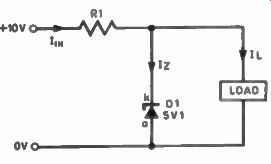
Fig. 1. Simple Zener diode application.
A series limiting resistor is needed with the Zener diode. Take a look at Fig. 1 which depicts a 10V d.c. voltage connected to a resistor R1 and a Zener diode D1. Note how the Zener diode is "reverse biased" to produce a steady voltage, the value of which depends on which Zener diode you pick. They have a tolerance on their values, too, typically ±5%. The Zener diode we chose was a 5.1V type (e.g. a BZY88C5V1 which is rated at 500mW maximum power dissipation)--which means that it will produce a 5.1V reference voltage under suitable conditions. A load is shown which could per haps be a 5V logic circuit.
The resistor R1 limits the total current flowing, in order to prevent destruction of the Zener. The current I_IN which flows through the resistor, then splits into two paths. Iz is the current flowing through the Zener diode, and I_L is the current flowing into the load. It follows that IN = IZ + I L. Let's assume that the load draws a constant 25mA i.e., I_L = 0.025A.
Before calculating the required series resistor, we need to bear in mind that a nominal current needs to flow through the Zener too. We can decide this figure ourselves and we have to pick a reasonably small value for Iz to ensure that the Zener's power rating is not exceeded. Let's say that Iz = 5mA. So with 5.1V appearing across the Zener and 5mA flowing through it, the power dissipated by the Zener diode is (P= I x V) 0.0255 Watts or 25mW, well within its 500mW rating.
By Ohm's Law, the resistor value is then equivalent to the required voltage drop across it (which is 10V-5.1V = 4.9V) divided by the total current 'IN flowing through it--which is 5mA + 25mA = 30mA. So in this simple circuit you could use a series resistor of 163 ohms (4.9/0.03), if one existed. You would use the nearest preferred value down instead, say 150 ohms.
Now double check. Using a 150 ohm resistor means that more current than we originally intended will flow through the resistor, although the voltage across the resistor won't change because the Zener maintains a steady 5.1V. How much current flows through RI? Again, from Ohm's Law, the current will be I= V/R so I_IN=4.9V/150 which gives us a current of 32mA. Because the load still faithfully draws 25mA, the rest of the current flowing will be consumed by the Zener, which draws 7mA (instead of the 5mA we intended) and therefore will dissipate about 36mW (5.1V x 7mA). Still very safe.
The power dissipated by the resistor could be worked out using either of two formulae: P=IxV or P= I2R. It's roughly 160mW so a 250mW ( 1/4 W) type is fine. By reducing the resistance even more, the Zener current will increase accordingly. The maximum current which we may allow the Zener to draw is determined by its power rating.
A 5.1V 500mW Zener diode may pass no more than 98mA maximum (I= P/V). Surprise Supplies
Suppose the supply rises to 25V. The current flowing through the resistor will now be (19-9V/150 ohms) = 133mA. R1 will dissipate 2.6 Watts and will soon bite the dust. The Zener will dissipate 550mW so is now over-rated too. Yikes! The picture's more complicated when the supply voltage and/or the load current varies. Designers have to take into account "worst case conditions" when specifying the components. The resistor's power rating is peak when the supply voltage is at its maximum--but choose a resistor value low enough for the required peak load current to flow when the sup ply's at its minimum voltage.
The Zener's power figure is peak when the supply rail is maximum voltage and the load is at minimum current. For in stance, take a 5V Zener, and if the sup ply varies between 10 to 15V, the load varies between 20mA and 100mA. Assuming a nominal Zener current of 5mA, I reckoned that the resistor would need to be 47 ohms 2.2 Watts and the Zener would need to be rated at 0-96 Watts minimum to cope with the varying load and supply. See if you agree!
Low Voltage Monitor
Talking of voltage references, Clifford Beck of Co. Offaly, Ireland, wrote: "I have an experimental rechargeable lighting circuit which is charged by a wind charger, and I run a few lights from it.
Could you design a circuit to switch the lights off when the battery drops below 11.5V, so when the battery is fully charged the lights can come on again? I was thinking of using the 8211 integrated circuit." Thanks for the suggestion, Mr. Beck.
Presumably the idea is to prevent the lighting from flattening the battery until it has recharged again. It occurred to me that this might also appeal to caravanners, boating enthusiasts or campers, and the device concerned--the 8211 programmable voltage detector--is a really easy i.e. to use and is a neat way of monitoring the supply voltage level, or any other d.c. level for that matter.
There are actually two 8-pin d.i.l. devices available--the ICL8211 and the ICL8212. I'll describe both. They are almost identical except that the 8212 functions in the opposite manner to the 8211. Firstly Fig. 2 shows a basic under voltage alarm using the ICL8211. The chip monitors the supply by comparing it against an accurate internal 1.15V reference or "threshold". With the 8211, when the voltage at pin 3 is less than the 1.15V reference, the output (pin 4) goes low and sinks typically 7mA in this state--it's current limited by the i.c. so I added an led. D1 as shown, with no series resistor being necessary.
Hence, when pin 3 is less than 1.15V, the l.e.d. lights. A potential divider is needed (R1 and VR1) and is calculated so that the voltage at pin 3 will fall below 1.15V when the supply voltage itself drops to the required level. In our case, the rail is assumed to be 12 V d.c. or more but an alarm/cut out is required when it falls to 11-5V or so, the exact alarm point being set by VR1.
The i.c. only consumes 20µA typically and the potential divider resistance can be set for 50µA current flowing through it, or even less, hence the circuit itself has negligible loading on the supply rail. The supply voltage can be up to 30V absolute maximum.
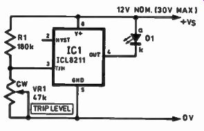
Fig. 2. Low voltage alarm.
Sister Chips
The complementary ICL8212 device has two major differences: its output is not current limited (35mA sink, maxi- mum), and the output goes low when pin 3 is higher than 1 -I5V. This is probably more suitable for our application because we could just add a pnp transistor driver to the output, see Fig. 3.
Transistor TR1 is a pnp Darlington power transistor which turns on when pin 4 is low (pin 3 > 1.15V). The load shown here is just a relay which in turn switches the lighting, but TR I is rated at up to 10A and could easily drive a load directly. By adjusting VR1, when the supply rail is higher than the desired switching level (11.5V, Mr. Beck specified), then pin 4 is low--this is equivalent to the "alarm state" of the 8212--there fore the transistor is on. When the sup ply rail falls, eventually dropping below 11.5V, the potential at pin 3 drops below 1-15V and thus the output goes high.
TR1 turns off, switching off the lights! The circuit consumes little current under these circumstances, preserving the battery. It's probably easier to use the 8212 this way since all it then needs is a single transistor to directly drive the load. Hence we're actually using the 8212 to detect not a fall but a rise in voltage--when the supply rail exceeds 11-5V this is deemed the "alarm" and is used to turn the lighting on.
It's possibly worth introducing some hysteresis--a difference in the switch on and switch-off levels which prevents the load from constantly jittering. Pin 2 (hysteresis) can be used to introduce positive feedback by connecting it via a resistor to the potential divider. (The hysteresis pin is actually a complement of the output pin but it only sources some 20µA.) This means that the load won't forever be switching on and off when the circuit is just on the threshold level. Try it by adding a resistor--say 1M or 2M2--between pins 2 and 3.
Finally, whilst the ICL8211/8212 are bipolar devices made by Harris, improved CMOS versions of both chips are produced by Maxim--the MAX8211 and MAX82 12. They're only suitable for supply rails up to 16.5V though, the CMOS chips have much lower quiescent currents and the resistance of the potential divider network can be greatly increased to reduce the supply drain. Also the hysteresis pins source a useful 10mA. All four devices are available from Farnell (0532 636311)--Part Numbers are ICL821?CPA or MAX82!?CPA2.
Fig. 3. Low voltage trip circuit using ICL8212. RL4 rail exceeds trip level. TR1 can provide up to 10A drive, only operates when supply.
Suggestions for experimenters: design using an opto-isolator driven straight from the ICL8211 output, or maybe use the hysteresis pin of the MAX8212 (goes high when the threshold exceeds 1.15V) to drive an npn transistor or MOSFET to power the lights.
Soft Where? D. Evans of Gwynedd asks if there is any suitable educational software to run on a PC. Electronics Principles from EPT Educational Software is now available from the EPE Direct Book Service and a demo disk costs £2--see advert else where in this issue. It's definitely worth checking out if you're looking for an imaginative and concise way of learning the basics of electronics using a computer as a learning aid.
C.L. Quay from Malaysia wrote to say he's delighted with the hi-fl 'speaker de thump which worked a treat (see last month). I read every letter but unfortunately I cannot guarantee an individual reply or advise on the repair or modification of commercial equipment. If you have a suggestion or idea which might interest other readers, then write to me at Circuit Surgery, Everyday with Practical Electronics, 6 Church Street, Wimborne, Dorset BH21 1JH. See you next month!
(adapted from: Everyday Practical Electronics, Jan. 1994)