Finding and repairing the source of minor current leakage can prevent more serious trouble later.
By Christian H. Acard, AEMC Corporation president
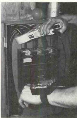
------- Clamp-on probe encloses all current-bearing wires except a static
ground, and the reading is obtained from the meter unit that's strapped to
a wrist.
Insulation failure in electrical systems and equipment can lead to a number of unfortunate consequences. At the least, an undetected insulation failure that leads to gradually increasing ground fault current can result in an over-current situation that trips a circuit breaker, causing loss of production time and untimely maintenance procedures. At worst, such a condition may result in electrocution or tire.
Timely detection of leakage cur rents can isolate faulty equipment and allow maintenance to be per formed before a breakdown occurs.
Detecting leakage currents
A clip-on current leakage detector provides a relatively simple and convenient method of detecting leakage currents by measuring the leakage current-that shunted to ground-caused by an insulation fault (Figure 1). It enables the operator to locate failures quickly, when or even before they occur without shutting down equipment or spending hours troubleshooting.
The unit is a clamp-on current transformer that is sensitive to ac currents passing through it. One such device features two ranges: 300 mA and 3 A, full scale.
When a generator supplies an ac load through a pair of wires in an insulated cable, the current going out on one wire is equal to the current coming back on its re turn. Their sum equals zero. A ground fault changes this equality, and the leakage current detector picks it up, measures it, and indicates the severity of the fault causing the unbalance. But it can only give a reading other than zero if it does not enclose the ground conductor, as shown in Figure 1. It makes no difference whether the circuit is single- or 3-phase; 3 or 4-wire; balanced or unbalanced.
The detector sees the leakage current to ground.
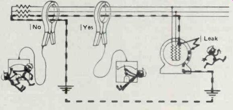
Figure 1 Clip-on ac current leakage detector measures leakage current caused
by insulation fault.
How to interpret measurement
A single-phase installation with a ground is shown schematically in Figure 2. The numbers indicate the amplitudes of the currents in the different conductors. Since this installation has no faults a detector clamped around the cables at points A, B, C, or D will read zero.
A fault in a motor, as shown in Figure 3, will cause a reading of 1 A at point A (the difference between 16 and 15 A), indicating that there is a fault downstream.
At point C, the detector reads zero. Therefore, the fault is not in the oven. At points B and D, it reads I A, showing that the fault is in the motor. If it gets worse, the leakage current will increase and the circuit breaker will trip. This motor must be disconnected immediately and repaired.
In a 3-phase installation (Figure 4A and 4B) the principle is the same. But here it is necessary to pass all active conductors through the detector, including the neutral if one is used. If this is done properly, the detector will read zero if there is no current leaking to ground. If it reads something other than zero, there is a ground fault that should be repaired.
Operating method
To locate a fault quickly, begin troubleshooting at the incoming low-voltage distribution header, successively checking each feeder.
If there is a ground fault, follow the feeder downstream, branch by branch, to the machine with the problem, as shown in Figure 5.
For preventive maintenance it is useful to take measurements to create a history of the quality of the insulation. If you detect a fault current that is very low initially but increases from day to day, this means that electrical failure is imminent and should be taken care of during the next planned maintenance shutdown.
For best results, center the conductors in the detector's clamp.
Also, check that the edges of the jaws are perfectly clean and that they close tightly. Try to avoid placing the conductors near the gaps, and group them as much as possible.
------------
Importance of eliminating leakage currents
A severe short seldom occurs between power wiring and earth ground without the preliminary warning of a small leakage current that increases gradually over a period of time. If this warning is ignored, the leakage be comes worse and finally might injure or electrocute an employee, start a fire, or halt production while major re pairs are made. By contrast, repairs to the wiring made during the stage when the leakage current is too small to trip an overload breaker usually are easy and inexpensive.
Formerly, the problem was to find these shorts before they became serious. The standard measurement in the industry is to employ a current meter which clamps around the insulation of a single wire and reads the current in amperes, sometimes hundreds of amperes.
However, a clamp meter usually can't measure small leakage currents. When placed around the hot wire that carries power to the load (and the wire with leakage to ground), the reading might be 900 milliamperes (0.9A) higher than when the clamp meter is measuring the return wire current. Unfortunately, a difference of less than 1A out of 239A is too small to be read with any accuracy.
Perhaps the best answer is a specialized clamp-on ac current-leakage detector, such as model 126.100 from AEMC Corporation. It has a 0.3A full scale range and a 3A full scale range. The low range permits leakage readings down to 0.030A. In most cases, it is not necessary to make any changes in plant wiring during these leakage measurements.
---------------
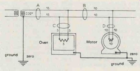
Figure 2 Zero reading of leakage detector indicates that there are no faults
in this circuit.

Figure 3 Readings of leakage detector at points A, B, C and D isolates fault
to motor.

Current-leakage detector can measure fault currents even when the conductor
are in conduit.
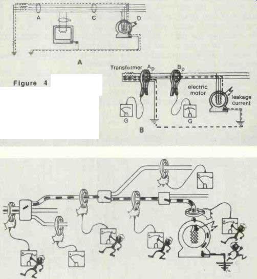
Figure 4 In 3-phase systems, leakage detector must enclose all current-carrying
conductors, including the neutral.
Figure 5 Fault location is isolated by following feeder branch-by-branch downstream.
Carelessness can affect the magnitude of the reading, depending on the current carried in the conductors. In certain cases, this change requires an interpretation. It is important to remember that the absolute value of ground current is not important. All you need to know is whether or not the reading is zero.
Checking out various cables
Older installations have a wide variety of electrical distribution systems. Cables are clamped to walls and pass through metal conduits, and there are many cases where shielded cable is installed during revamping of an area or an addition to the building.
For cables clamped to walls, first detach the cable and pull it away from the surface at several points, so the clamp can surround the conductors. Those locations become the test points where you will take periodic measurements.
Cables enclosed in metal conduits not grounded Cables enclosed in metal conduits not grounded are no problem-just apply the clamp around the conduit. It takes more than a metal tube to block the measurement.
Cable with a metal shield can be handled the same way as metal conduit.
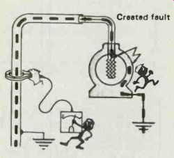
Figure 6 Where shield is not connected to motor frame, fault current can
be detected by clamping instrument around shielded conductors.
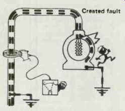
Figure 7 If shield is connected to motor frame, reading should be taken at
a point where shield is not enclosed by instrument clamp.
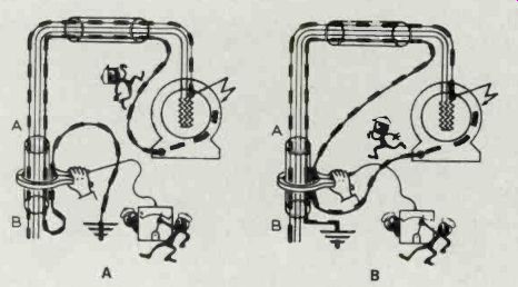
Figure 8 Another way to use the detector on shielded cable is to loop the
shield twice through the detector's clamp.
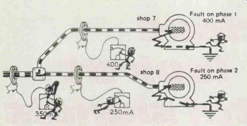
Figure 9--On 3-phase systems faults add vectorially, reading may be misleading.
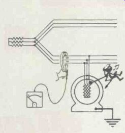
Figure 10--On insulated-neutral systems use of leakage detector may require
special techniques.
Cable enclosed in metal conduits grounded
Whether the shield or the conduit are grounded may or may not present a problem. It depends on the terminal connections, as well as the number and type of ground connections along the cable.
In Figure 6, the detector senses the fault because the shield is not connected to the motor frame and the leakage current cannot flow back through the detector.
In Figure 7, however, the instrument cannot see the fault because the shield is connected to the motor frame, letting the fault current re turn through the detector and causing it to read zero. Try to take the measurement where you can avoid enclosing the shield in the clamp, such as at the nearest control panel or inside connecting box of the motor.
One way to get around this shielded cable problem is shown in Figure 8. Here, the shield is looped through the detector twice, so that the reading will be that of the fault current.
Type of network
Inspecting grounded neutral installations
It is easy to take measurements on this type of network, where major faults trip the circuit breaker. Here, the detector can sense minor faults, so repairs can be made before the problem gets worse.
The inspection method is the same for a single-phase. Just re member that on a 3-phase, the cur rents add accordingly to the vector sum law.
The detector measures the vector sum of the enclosed currents. If you have, for example, a 400 mA fault and a 250 mA fault on the same phase, you will read 650 mA. But if the two faults are on different phases, they add vectorially and may even sum to zero.
Suppose you have two faults, as in Figure 9: 400 mA on a machine in one shop and 250 mA on another machine in another shop.
The vector sum is not 650 mA, but 350 mA. If you switch off the machine with the 250 mA fault, the reading increases, indicating faults on different phases.
Neutrals grounded through impedance
Follow the procedure as for a grounded neutral installation but with care. When the neutral is grounded through an impedance, a fault-even a serious one-may not trip the circuit breaker, and thus allow the shop to keep operating.
Insulated neutral installations
The instrument does not work (see Figure 10) but the trick is to treat the insulated-neutral installation as an impedance neutral during troubleshooting. A temporary artificial neutral can be made with three equal impedances and ground it.
Certain precautions must be taken to avoid accidents. Be sure to select impedance high enough so that tie first true fault does not produce an excessively high leakage current which could raise the ground potentials to a dangerous level.
Also see: Comparison of VOMs, VTVMs and DMMs