If the main voltage malfunctions, it may keep the set from starting up, or it may cause the set to shut down. Here's how to determine if the regulator is the culprit.
By Gregory D. Carey, CET [Carey is an application engineer at Sencore. He has run more than 800 seminars for service dealers.]
This is the last of a 3-part series dealing with the horizontal output circuits of modern TV receivers. Part I explained how shutdown circuits operate and the best way to find the cause of shutdown.Part II discussed what to do if the circuits never get started in the first place. This time, we'll see how to isolate problems related to the power supply and regulator circuits. Combining all three should help you isolate any problem related to the output stages.
The first two installments of this series described how to troubleshoot problems in the startup and the safety shutdown circuits in modern TV receivers. This article will explain how the main voltage regulator can cause a shutdown or a startup problem. The first section explains how the troubleshooting from the first two articles isolates regulator problems. The second section explains how various kinds of regulators work. See Figure 1 for a diagram of the three loops that must work correctly for a modern TV set to operate.
How the regulator causes shutdown
The regulator is often the cause of shutdown. If it applies too high a voltage to the output transistor, the high voltage and the yoke current can climb too high. One of the safety detectors should sense this and cause a shutdown circuit to kill the horizontal output circuits.
The first article states that the best way to identify the cause of a shutdown is to monitor the collector of the horizontal output stage when you first apply power to the receiver. This calls for test equipment with enough protection to monitor voltages as high as 1,200V. When the horizontal circuits operate correctly, the voltage reading at the collector should be the regulated dc level specified on the schematic. It should also have pulses, about 12µs wide, that repeat every 63.5µs. The pulse amplitude varies from one receiver to the next, but it is normally between 700VP_P and 1,200Vp_p. A chassis with a shutdown problem produces flyback pulses until the safety circuits take over. The circuits either shut down the ac drive to the output transistor or its dc power supply.
After confirming a shutdown, separate the regulator from other possible problems. Reduce the ac line voltage to less than 90V with an isolated, adjustable ac power supply. The lowered voltage reduces the dc at the regulator input to a voltage below its normal output. Because the regulator cannot boost the voltage, this gives you manual control of the voltage powering the output stage. (See Figure 2.)
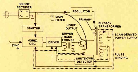
Figure 1. For the horizontal circuits to operate, three loops must work correctly:
the main power loop (solid line), the scan-derived loop with its startup circuits
(dashed line), and the safety shutdown loop (dotted line). (Schematic courtesy
of Sencore.)
If the set operates at this lower voltage level, you can make some tests on the collector signal to eliminate ac conditions as the cause of the problem. If the scope CRT shows that the flyback pulse is less than 12µs, for example, a capacitor between the emitter and collector of the output stage is probably open. If the pulse is poorly shaped, suspect a bad flyback or a shorted flyback load. If the pulse has the correct waveshape, monitor it while increasing the ac line voltage.
Now, monitor the do level while you observe the flyback pulse. The dc should increase as you raise the ac line voltage until it reaches its normal output voltage. If it continues to increase beyond the normal level, you know that a bad regulator is causing the shutdown.
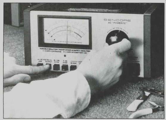
Figure 2. Use an adjustable, isolated ac power supply to reduce the voltage
to the receiver.
This gives you manual control of the voltage regulator, which lets you find what is causing the circuit problem.
How the regulator prevents startup
The regulator also can be the cause of a startup problem if its output is too low to operate the output stage. To further complicate matters, some receivers ...

Figure 3. Set the scope's input coupling switch to "DC" to tell
whether power is still present immediately after it is applied. If so, the
line will move from the position set before applying power. If your scope
has a digital readout, use it to confirm the correct dc level.
... use a shutdown circuit that kills the regulator, which makes it important to monitor the collector of the output stage from the very first moment power is applied.
A dc-coupled oscilloscope lets you test for dc during the first few seconds. Before applying power, set the scope's input coupling switch to dc and set the trace position near the bottom of the scope face. Set the vertical attenuator to the highest volts per division setting.
You know that dc was present if the trace moves up from its resting position when you apply power. If the trace then settles back to its original position, the regulator has gone into shutdown. If your scope can monitor the dc level digitally, use it to check the resulting voltage after the initial excitement dies down. Also, watch for flyback pulses. If they build and then collapse, the set started and was then shut down. (See Figure 3.) Any dc you measure at the collector while the set is shut down can be misleading. The voltage usually will be too high because the output stage is not drawing current. Reducing the voltage and then increasing it slowly lets you confirm whether the regulator is working while the output stage is pulling power.
Now that you know how the regulator can cause shutdown or startup problems, let's look inside several typical regulator circuits to learn better ways to troubleshoot them.
Nothing beats a zener
Nearly all voltage regulators use a zener diode as a reference. The zener, however, needs some help to control the high power used by a TV output stage.
Before we look at the helper circuits, let's review how a zener regulates. (See Figure 4.) When reverse biased, a zener acts like an open circuit as long as the voltage across it stays below its breakdown level. If the voltage exceeds the zener's rating, it begins to draw more current in an attempt to hold the voltage across it to a fixed level. As the current increases, the diode dissipates the excessive power as heat. If too much current flows for too long, the heat destroys the diode.
The circuit that uses the zener needs to limit the maximum current to prevent the zener from burning out. Most circuits use a series resistor. The resistor and the zener then form a voltage divider, with the difference between the zener voltage and the raw supply voltage dropping across the series resistor.
Some small power supplies use a zener as the sole regulator. There are, however, two limits to the zener regulator.
First, the zener runs out of regulation range if the power dissipated by the load is equal to or greater than the zener's power rating. This power limitation worsens if the power drawn by the load varies greatly. The zener/resistor regulator also does not work well if there are large variations in the applied voltage, because the series resistor always drops some voltage, even if the zener is not conducting.
A television has all these conditions.
The television draws 100W or more, depending on many variables, including the brightness of the picture and the loudness of the audio. Moreover, ac line voltages may change from 90V to 130V as the power lines swing between brownouts and peak voltage. Therefore, the zener needs some help.

Figure 4. Zener diodes can be used as a regulator as long as the load has
low power requirements and the input voltage does not vary over too wide of
a range. (Schematic courtesy of Sencore.)

Figure 5. The addition of a power pass transistor increases the zener's current
capability. A single power transistor typically provides a 10-fold increase
in current compared to the zener by itself-not enough to regulate most TV
receivers. (Schematic courtesy of Sencore.)
The pass transistor
A power transistor is often used to assist the zener diode. The zener is placed in the base, with the transistor acting as a follower. The result is a multiplication of the zener's power rating. (See Figure 5.) The transistor helps the zener diode regulate higher current levels. It is somewhat limited, because most power transistors have a beta gain of around 10.
You would need an expensive 10W zener to regulate a 100W load.
The multiplication effects are enhanced if more than one transistor is used between the zener and the load; this allows a small zener to be responsible for controlling large power levels.
However, cascading transistors create a new problem: As more and more transistors are used between the load and the reference, there is less responsiveness with changes in load current.
One solution is to use a feedback system. (See Figure 6.) The voltage at the regulator output is fed back through an amplifier and then compared to the zener. The results of this comparison are then fed to the power transistor for final control. Although this results in a very tight control of the output, it also complicates troubleshooting, because problems in the feedback amplifier, the pass transistor and its driver, or in the zener can all cause the regulator to put out the wrong voltage.
Increased efficiency
Regulation power transistors all have another problem: They are linear devices that regulate by changing the resistance to current passing between the collector and the emitter. They must waste excess power as heat. They must, therefore, be mounted on large heat sinks to allow the excessive heat to be conducted to the surrounding air. The wasted heat causes the receiver to use more power than really needed.
The best way to identify the cause of a shutdown is to monitor the collector of the horizontal output stage when you first apply power to the receiver.
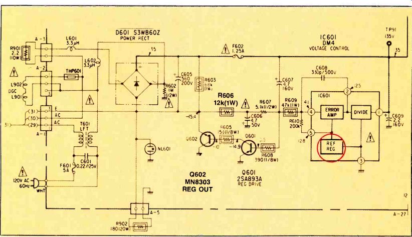
Figure 6. More elaborate regulators such as this one need feedback amplifiers
to sample the output voltage and control the power transistor. Notice that
a zener diode, inside 2601, still serves as a standard for comparison. (Schematic
courtesy of Sony.)
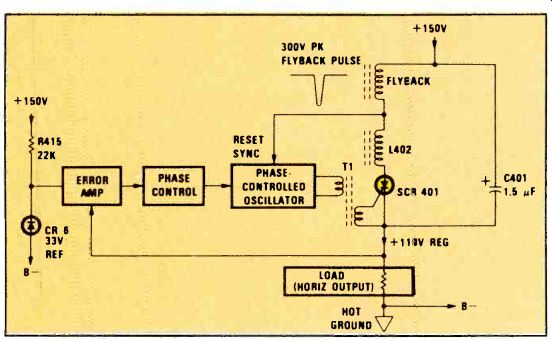
Figure 7. This SCR regulator is more efficient than a power transistor because
much less power is wasted as heat. The oscillator fires the SCR at different
times during horizontal trace time, depending on the amount of power needed.
Firing the SCR earlier provides higher power. (Schematic courtesy of RCA.)
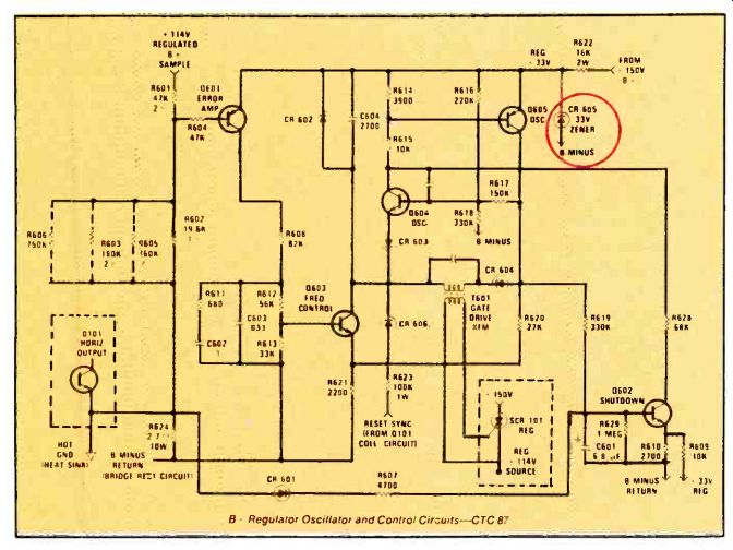
Figure 8. This schematic shows an actual regulator oscillator and driver.
Notice that an accurate zener still serves as the main voltage reference.
(Schematic courtesy of RCA.)
To correct this, some manufacturers have replaced the regulator transistor with a silicon controlled rectifier (SCR). An SCR is not a linear device. It is an electronic switch that is either off or on.
(See Figure 7.) Because there is no in-between state, it wastes less power. But there must be some way for this on/off device to compensate for many load and line variations.
The SCR compensates by varying the time it conducts; if it is switched on for longer periods, the load receives more power. This switching is done with an oscillator that is synchronized to the 15,734Hz horizontal output circuit. The oscillator fires the SCR at some point during the horizontal trace time. If the regulator needs to reduce the output power (such as when the television has a black picture or the line voltage is high), the SCR fires later in the trace time. If the regulator needs to increase the power, the oscillator fires the SCR earlier. The oscillator compares the regulated output to a precision zener diode to determine this timing. (See Figure 8.) Once the SCR is fired, it will stay on until the voltage between its anode and cathode drops to zero. An extra flyback winding, wired in series with the SCR, provides a pulse to turn off the SCR. The flyback pulse reverse-biases the SCR during each time the beam retraces. The SCR remains off until the oscillator turns it on, sometime during the trace time.
Startup and shutdown problems are tough to find because of the way the circuits operate. A shutdown happens so fast that it often looks like a startup problem. Three closed loops intertwine, which turns your troubleshooting into a wild goose chase. Voltage regulator problems can also cause either type of problem.
Two techniques solve these problems.
First, watch the collector of the output transistor to monitor both ac and dc conditions during the first few seconds of operation. Second, reduce the ac line voltage so that you have manual control over the regulator circuits. Then, move slowly through the circuits until you've isolated the problem.
Also see: Computer servicing---Special report introduction