The PA81 stereo power-amplifier analyzer
By Carl Babcoke --- C. Babcoke is the Consumer Servicing Consultant for ES&T.
The model PA81 power-amplifier analyzer from Sencore dynamically tests stereo amplifiers with power outputs up to a total of 500W, measured according to Electronic Industries Association / Institute of High Fidelity (EIA/IHF) standards. Many unique testing functions and techniques also are included for quick, dependable troubleshooting of hi-fl stereo circuits.
Here is a partial list of features and functions:
• Twin autoranging analog meters (one for each channel) each have six ranges with LED range indicators.
• The user can measure rms audio power to 100W per channel for continuous operation or 500W for intermittent operation.
• The automatic dcV-Balance monitor system has an LED for each channel.
The LEDs light red and blink every second if more than ± IV appears at the in put to the dummy-load resistors. A re lay also disconnects the analyzer's malfunctioning input signal from its dummy resistor within 50ms.
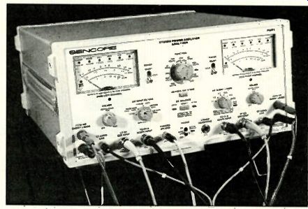
(above) The front-panel layout is both practical and attractive. All operating
switches and controls are placed widely apart, leaving plenty of working
room. A black dot on each knob plus the large black letters and figures
are so legible that you can read all functions and ranges from 5 feet
or so.
--------------
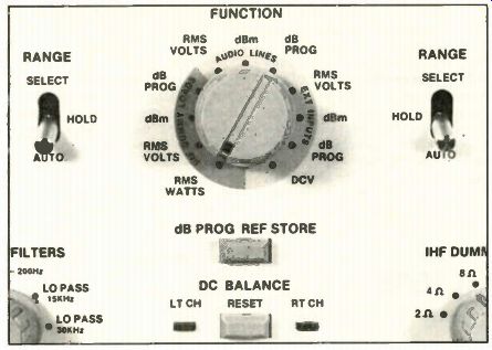
All three external components of the dcV-Balance feature
are located on the front panel be low the Function switch and the dB-Prog-Ref-Store
push button. A dc voltage higher than ± 1V from the amplifier that
is connected to the dummy-load resistors opens the circuit be tween amplifier
and load resistors. Also, an LED blinks to warn of a defect and show
which channel is affected. The two Range switches are between the Function
switch and the meters on both sides. Each switch controls the method
of range selection for its respective meter.
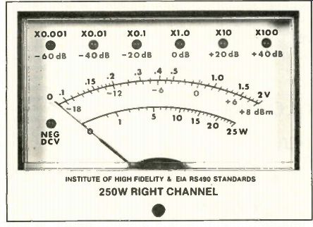
----- Analog meters supply all numerical readings. One
advantage of the electronics that drive the meters is the need for only
three calibration scales on two arcs. Another advantage is the nearly
linear dB calibration scale. Also, an overload does not "pin" the
pointer.
• An open circuit or one of five dummy-load resistances can be selected by the Dummy-Loads switch.
• The user can choose one of four input-frequency filters or no filter.
• For signals entering the left or right audio-lines inputs, the Function switch offers ac measurements of rms acV, dBm or dB Prog (programmed) at 10k( in put impedance. The purpose is to test standard audio lines.
• For signals entering the external in puts, the Function switch can select rms acV, dBm, dB Prog or dc-voltage measurements. This is the only function having dcV. These functions are for signal tracing and troubleshooting almost any where. Input impedances for ac voltages are MU; dc voltages have 15Mft.
• For signals from the dummy-load resistors (amplifier's output), the Function switch offers rms watts, rms acV, dBm and dB Prog.
• All types of decibels have the same voltage or power ratios, but those with letters following the dB have specific reference levels. Most decibels in the analyzer are measured by the dBm standard where 0 dBm equals 1 mW across a 6000 load (which calculates to 0.775Vrms). Programmed dB readings depart from the zero reference of the dBm standard and, therefore, are given in dB, not in dBm.
• An Over Temp indicator lights when the internal temperature becomes excessive. A fan gives sufficient air circulation to maintain a safe temperature. A total audio power up to 200W is dissipated continuously in the dummy-load resistors. Higher powers require limited operating times.
• Two internal speakers with volume controls, driven by internal amplifiers, are available for each channel. These volume controls are not entirely responsible for controlling the huge span of sound from a whisper to perhaps +35dBm (45Vrms) at 250W per channel that is obtained at maximum power. Sencore has provided a tie-in with the autoranging circuitry so both channel volumes are reduced or increased in 20dB steps.
• Power for the unit can be obtained from one of three sources: a power adapter that operates from 105/130Vac lines and can recharge the optional battery; a fused cigarette lighter plug for 12V operation; or a rechargeable battery pack, which is good for about five hours of operation.
• The analyzer comes with a 13-page instructional pull-out chart.
The dB programming feature When you want to use a reading from the unit you're testing as a 0-db reference for a measurement at another test point, you use dB Prog. Whatever signal level is being measured when the Store button is pushed becomes the new 0dB reference, and subsequent dB Prog readings are relative to this new 0-dB. Both channels undergo programming simultaneously, but they can have different 0-dB references.
This feature is useful for troubleshooting, such as checking the gain of a transistor or the gains or losses of cascaded stages.
Remote operation
Tests can be automated by using the model 1B72 IEEE 488 bus-interface, which connects between the PA81 and a controller or automated system.
In the basic "talker" mode, a technician selects the desired functions and ranges. The resulting readings are sent to the IEEE interface through an 1E233 bus cable.
As a "listener." the PA81 receives commands from the controller to select certain functions or ranges. In this mode, the panel controls are locked out electronically, and the controller automatically steps the unit through the required tests.
The third mode is a combination "talker/listener." All functions except the dummy-loads resistances and the volume controls can be controlled via the bus interface.
Versatile external inputs
In several important ways, the two external inputs are different from the other two functions from the same switch.
First, dc voltages can be measured along with the usual rms acV, dBm and dB Prog functions. Also, the Ext-Input grounds are not connected to each other or to chassis ground. These independent grounds add flexibility during troubleshooting. For example, one input probe can be connected across a transistor's base resistor and the other across its collector resistor without one reading having any effect on the other.
The isolated grounds also help broaden the areas suitable for dcV testing be cause both external probes can be used on the same channel.
Isolated grounds For maximum safety and flexibility, the unit has several sets of isolated grounds. First, the conventional chassis grounds: The two audio lines cables, two scope cables, one stereo jack and the chassis-ground post are connected to the frame and chassis ground. The two sets of binding posts for audio power input to the dummy-load resistors are not grounded to the chassis, nor to each other. The two external-input grounds are not connected to anything on the panel, the chassis ground or to each other.
Unusual meters--Although the twin analog meters might appear ordinary, they're not. The meter faces are only a small part of each meter's circuitry. IC-based circuitry controls the meters. These ICs are why some functions can have as many as six ranges, although each meter's face has only three scales.
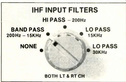
-------- Specifications for the four input filters are in agreement
with the IHF standards.
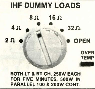
--------- Five load resistors of IHF values are selected by the IHF
Dummy Loads switch for both channels. Each resistor can tolerate power
dissipation of 100W (per channel) indefinitely, and for gradually reduced
times up to a maximum of 250W per channel for five minutes.
Self-test at power on Immediately after power is switched on, the meters produce quite a visual show. The first time I used the meter, I noticed that the display activated all the LEDs, and the meter pointers moved smoothly from zero to maximum and back to zero. I initially thought this was caused by power-on surges, but nothing appeared to happen randomly. I concluded that this was a self test.
Autoranging surprises
With analog autoranging in this unit, one of the six LEDs shows the range, and the reading is shown by the pointer position vs. the range value. Both digital and analog autoranging are equally easy to use and to obtain a reading. With analog, the pointer can show quick changes of audio, but without the frantic search for a stable reading that is common with digital meters.
The scope's input level and the internal-amplifier sound volume are tied to the steps of the autoranging. This eliminates many adjustments of scope gain controls and the volume controls.
Each meter has a Select/Hold/Auto toggle-type, 3-position range switch.
Moving the toggle to the down position, where it locks, activates the autoranging for that channel. With Auto, the analyzer selects the proper range and stops there during a measurement.
When the probe is removed from the circuit, the meter down-ranges to the minimum range and remains there until the next test.
The switch's center position selects the range-hold condition that locks in whatever range is in use, thus overriding the autoranging. When a specific range is needed, use the Select position of the switch to move the range multiplier LED up one position for each time the momentary-contact switch toggle is moved upward.
Manual ranging by the Select switch operates only for up-ranging. During Auto fully-automatic operation, however, the internal circuits supply down ranging as well as up-ranging.
Learning about autoranging
Up-ranging is triggered when an in creasing signal reaches the +8dBm calibration line on the dBm scale, regard less of the range in use. This up-ranging operation ends with the next higher dBm range at the -12dBm line.
Down-ranging is triggered when the signal level is decreasing and reaches the -15dBm line on the dBm scale, regardless of the range in use. Down ranging ends on the next-lower range at the +5dB line.
Coverage from one up-ranging to the next is 20dBm (12+8=20); the cover age between down-rangings also is 20dBm (15+5=20). These ranges give complete decibel coverage. However, the dBm scale has calibrations down to -18dBm, so there are three extra dBms that can be used in manual operation by the Select and Hold switches.
The difference between -12dBm and -15dBm at the low end and +8dBm vs. 5dBm at the high end of each range is the hysteresis that prevents unstable autoranging triggering.
Input IHF filters
Five positions are available from the IHF Input Filters selector switch:
• No filters provides a flat frequency response from 0Hz to 200kHz.
• Bandpass filter circuits pass all frequencies between 200Hz and 15kHz.
• Hi-pass filter circuits pass all frequencies between 200Hz and 200kHz.
• The lo-pass 15kHz filter passes all frequencies below 15kHz, including the below-200Hz hum area. This filter forms a good pair with the bandpass filter for measuring 120Hz and 60Hz hum in the amplifier's output.
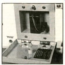
-------- When 120Vac power is not available, a BY234 rechargeable
12V battery can be used to power the unit for up to five hours.
• The lo-pass 30kHz filter passes the audio spectrum below 30kHz. It is useful for removing digital-clock noises above 30kHz without obscuring the CD test material or the music's harmonics.
One filter application is removal of the 19kHz pilot carrier from FM receiver audio signals. Either the 20Hz 15kHz bandpass or the 10Hz-15kHz lo pass filters will reduce the 19 kHz carrier's amplitude by 30dB or more. An other filter (30kHz lo-pass) removes the digital-clock noise from the audio signals of compact discs, providing better accuracy during separation tests. There is no hum filter, but the hum can be calculated easily.
Dummy loads
The dummy-load resistors have the following specifications:
• Values are 20, 4 ohm, 8 o, 16 o and 32 ohm, ± 1% (IHF specifications).
• Position six of the Dummy-Loads switch opens the load circuit. This feature helps identify tendencies toward oscillation or other instability, which of ten is more severe with no load.
• The reactance of any dummy-load resistor is lower than 10% at all frequencies lower than 200kHz.
Lab tests--I decided to test two amplifiers: a 45W per channel, transistorized AM/FM-stereo with digital tuning and readouts; and a 30-year-old tube amp.
(For a detailed description, see the side bar.) I used the analyzer to perform minor repairs on this amp, which gave me an opportunity to use rms watts, the audio input lines and the external inputs, plus functions of rms volts, dBm and dcV during the repairs.
Although the analyzer can perform many tests well, the capability to test stereo-amplifier high-wattage powers easily and accurately is perhaps the most important.
Here is a streamlined method for testing the powers of stereo amplifiers, including the pre-setting of amplifier controls and analyzer adjustments:
• Connect an external audio generator to the amplifier's AUX inputs.
• Connect the amplifier to the dummy-load.
• Adjust the amplifier's tone controls, including subsonic and loudness, for flat bass and treble response.
• Adjust the Dummy--Loads selector to match the amplifier's rated output impedance.
• Adjust the IHF Input-Filters switch to 200Hz-151cHz bandpass.
• Rotate the Function switch to rms watts.
• With shielded cables, connect the PA81's scope outputs to your dual-trace scope's inputs.
-----------------
26
Repairing a tube-type amp
These waveforms were produced during final repairs of an old tube-type stereo amplifier. In the first photo, both positive and negative tips are rounded. That is typical of mild overload with tubes (whereas transistor amplifiers usually have sharper edges at the clipped tips of the sine waves). In the second photo.
notch distortion near the sine waves' vertical centers is excessive. In the third pho to, the sine-waves' positive and negative peaks of channel 2 (bottom trace) are not symmetrical, probably indicating one weak 6BQ5 output tube or stage. After the tubes were more nearly matched (no new ones were available), the powers of both channels and the waveforms were nearly identical, as shown in the second photo. Notches near the vertical centers were caused by the over-biased output tubes failing to draw current quickly enough at the beginning of each peak.
The notches disappeared and the flat tops tilled out as the power was slowly decreased. The third photo shows the un distorted sine waves produced by reducing the output power slightly.
------------------------
The actual amplifier-power measurements usually are performed quickly and easily according to the following steps:
• Slowly increase the signal level of the 400Hz sine waves while you watch the rms-watts range on both meters. These readings should increase slowly and re main approximately equal. Notice the up-ranging at 25W. Continue slowly in creasing the level until the scope shows a small amount of sine-wave peak clipping.
• Reduce the level until the clipping barely disappears. With or without clip ping, the sine waves should be free from oscillation, distortion or ringing.
Record the two wattage readings.
PA81 specifications
• The rms watts function for the stereo channels covers 0W to 250W in two ranges: 0-W to 25W and 0 W to 250W. The accuracy is ± 3 % of range full-scale at 1 kHz with an 8 ohm load.
• Dummy loads: 20, 40, 811, 160 and 320, ±1%, plus open; reactance lower than 10% below 200kHz; rated for 100W of continuous power or 250W of intermittent power per channel.
• Channel separation is better than 100dB at 1 kHz.
• rms volts covers 0.2mVrms to 200Vrms in six ranges for audio line and dummy-load inputs. For external inputs, the 0.2mV range is deleted. The accuracy of these ranges is ±2% of range full scale; the frequency response is 20Hz 20kHz at ±2%.
• dBm covers -'72dBm to +48dBm in six ranges for audio-line and dummy load inputs. The range from -72dBm to -52dBm is deleted for external in puts. Accuracy is ±0.5dBm at 11cHz; the frequency response is 20Hz to 201cHz with a variation of only ±0.2dBm.
• dc volts covers OV to ±200Vdc in four ranges for external inputs only. Accuracy is ±3% of range full-scale.
• Impedance of the audio line inputs is 101c0 paralleled by 100pF.
• External-inputs impedances are IMO for ac tests and 15Mil for dcV tests.
• Scope levels are 2V ± 5 % rms when the meters are reading full scale.
• Dimensions are 7"x14"x16.7" (HWD); weight is 15.8 pounds (17.2 pounds with battery).
• Power drawn from the 12V source is about 4.2W; from the 120Vac source, the power is less than 26W.