By Bert Huneault, CET
Huneault is an electronics instructor and head of the REE department at St. Clair College of Applied Arts & Technology in Ontario. Canada.
This article is part two in a series of articles on thyristors. In this part, we will focus on diacs and Shockley diodes.
In Part III, we'll look at unijunction transistors.
In Part I, we became acquainted with the properties of SCRs in dc circuits.
Let's now focus our attention on SCRs in ac circuitry, where the thyristor's ability to rectify is put to good use. After all, it's called a silicon controlled rectifier, isn't it? Rectifier action We'll start with a simple circuit, that of a static-switch (line-gated), half-wave rectifier. (See Figure 1.) With Si open, as in Figure la, no gate current can flow; therefore, the SCR re mains in the off state and no current flows through the load.
Next, let's close S1 and assume that line A is positive at this time. (See Figure 1b.) Gate current now flows from line B into the cathode, out of the gate, through D1, R1, S1 and the load to positive line A. Although limited by R„ this gate current is sufficient to fire the SCR just after the beginning of the ac cycle, effectively closing the cathode-to-anode circuit of the thyristor for virtually the full 180° of the input voltage's positive alternation. This accomplishes two things: First, the load becomes energized because heavy current now flows from line B, through the SCR and the load to positive line A; second, because the conducting SCR's anode voltage drops down to IV or so (in relation to common line B), gate current is automatically reduced to a negligible amount during the remaining portion of the positive alternation of line voltage.
Recall that gate current is no longer needed once the SCR latches on.
When the line voltage reverses in polarity, the SCR reverts back to its non conducting gate Half a cycle later. with line A positive again, the SCR triggers back on (as long as Si is still closed). Thus we get half-wave current through the load. The latter could be a dc mo tor or a heating element, for example.
Now let's open S1. If the SCR is al ready conducting at that instant, it continues to conduct (remains latched on until the end of the positive alternation in progress at the time). It then shuts down and the load is de-energized. Subsequent positive alternations of line voltage do not re-energize the load because gate current - necessary to trigger the SCR back on each time -- cannot flow with S1 open.
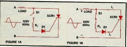
Figure 1. In this static-switch (line-gated), half-wave rectifier, when Si
is open, as in Figure la, no gate current can flow. The SCR remains in the
off state and no current flows through the load. When Si is closed and line
A is positive (Figure lb), gate current flows, firing the SCR and effectively
closing the cathode-to-anode circuit of the thyristor for virtually the full
180° of the input voltage's positive alternation.

Figure 2. In high-power circuits, switch S1 would be a troublemaker because
of intense arcing each time its contacts open and close.
In a static-switch, half-wave rectifier, Si does not interrupt the main load current.
Incidentally, diode DI is simply there to protect the SCR during negative excursions of line voltage. SCRs typically have a peak reverse gate voltage rating of only a few volts (e.g., 5V). The gate-to-cathode junction would therefore break down if it weren't protected by the series diode. A small silicon diode with a PRV rating of 200V or 400V is all that's necessary to prevent reverse gate current even during the peak of negative line voltage.
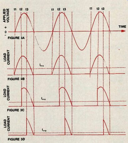
Figure 3. Varying the duty cycle of the SCR controls the average value of
anode current.
If a trigger pulse of ac voltage is applied so that the SCR is allowed to fire at time t1, the thyristor conducts for the entire duration of the positive alternations, resulting in a maximum value of average load current (Figure 3b). If the trigger pulse is delayed until time t2, there will be a shorter conduction period, reducing the average value of load current (Figure 3c). Delaying the trigger voltage until time t3 causes a further reduction in duty cycle and a corresponding reduction in average load current (Figure 3d).
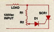
Figure 4. A variable-resistance circuit controls the firing angle from approximately
0° to 90°. If R2 is adjusted for maximum resistance, gate current may never
be sufficient to turn on the SCR: thus the load is turned off. As R2's resistance
is decreased, gate cur rent eventually reaches sufficient amplitude to trigger
the SCR.
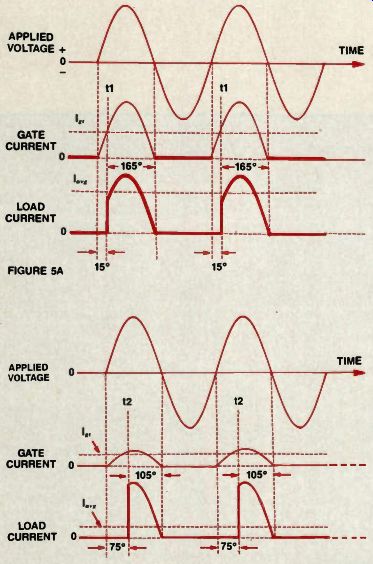
Figure 5. In Figure 5a, a relatively high amplitude of gate current causes
the triggering level (I„,) to be reached at time t1, at a phase angle of about
15°, resulting in about 165° degrees of conduction in each cycle and a fairly
high value of average load current. In Figure 5b, the amplitude of gate current
has been reduced by increasing the resistance of R2. The gate current doesn't
reach the triggering level until time t2, which results in a firing angle
of about 75° degrees (conduction angle of 105°) and a lower value of average
load current.
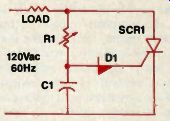
Figure 6. With the addition of an R-C phase shift circuit, up to 90° of phase
delay is gained. C1 charges through R1, delaying the triggering of the SCR.
An increase in the resistance of R1 increases the firing angle up to 180°,
at which point the thyristor remains off and no current flows through the
load.
Reducing the resistance of R1 allows C1 to charge more rapidly, triggering the SCR earlier and increasing the SCR's conduction angle and power in the load.
What's the point?
OK, so we've seen how this static switch, half-wave rectifier works. But isn't that circuit some kind of overkill? Couldn't we achieve the same results with just a simple half-wave rectifier di ode, as in Figure 2? After all, the SCR doesn't have the ability to control the amount of current flowing through the load in Figure 1. S1 can only switch the SCR on or off. As long as S1 is closed, the full amount of half-wave current (determined by Ohm's law) flows during each cycle. S1 can do the same in Figure 2, so why bother with Figure 1? The answer lies in the switch itself (S1). In low-power circuits it really wouldn't matter; therefore, the lower cost circuit in Figure 2 would be in or der. But in high-power circuits (with loads of hundreds of amps), switch S1 would be a troublemaker in Figure 2 because of intense arcing each time its contacts open and close. The large, costly switch would require frequent maintenance and/or replacement. In Figure 1, on the other hand. S1 does not interrupt the main load current; it only switches milliamps of gate current and should, therefore, enjoy long, trouble free service.
So you can see that the SCR, in effect, is a fast, solid-state relay featuring no moving parts and suffering from no contact bounce, no arcing, no pitted contacts. And it needs only a small amount of control power (gate current) to switch loads of hundreds or thousands of watts. Not a bad widget, huh?
Controlling average load current---In this section, we'll investigate an important advantage of the SCR: It is a controlled rectifier. The gate provides the means of adjusting the current smoothly over the full range from zero to the highest amount that can flow through the load.
Recall that once the SCR has fired, its gate has no control over the anode current. It's obvious that the thyristor cannot vary the amount of current flowing through the load during the rest of the ac cycle. However, the gate voltage can determine whether anode current flows at any particular moment.
For example, if a trigger pulse of ac voltage is applied to the gate in such a way that the SCR is allowed to fire at the beginning of each positive half-cycle of input voltage (at time t1 in Figure 3), the thyristor conducts for the entire du ration of the positive alternations, resulting in a maximum value of average load current. (See Figure 3b.) On the other hand, if we delay the application of ac gate firing voltage or trigger pulse - by means of a suitable phase shift or timing current - until time t2, there will be a shorter conduction period, reducing the average value of load current (lower duty cycle), as shown in Figure 3c.
Delaying the trigger voltage even further, until time t3, causes a further reduction in duty cycle and a corresponding reduction in average load current. (See Figure 3d.) So, by varying the duty cycle of the SCR, we can smoothly control the aver age value of anode current. This capability has practical applications in lamp dimmer and heat-control circuits and motor-speed control, to name a few. For example, if the load is the armature of a dc motor, controlling the average cur rent through it varies the speed of the motor. The lower the current, the slower the speed.
There are many types of firing circuits. Some use variable resistance or R-C phase shifting networks to delay the signal applied to the gate; others use magnetic amplifiers (saturable reactors), diacs, unijunction transistors (UJTs) or other devices to provide the necessary triggering pulses of gate current. But regardless of the type of control circuit used, the principle remains the same: The average value of load current is controlled by the firing angle of the SCR - the phase angle of applied ac voltage at the instant firing takes place.
Half- wave variable resistance phase control Figure 4 illustrates a variable resistance circuit capable of controlling the firing angle from approximately 0° to 90°. The gate circuit resistance (R1 and rheostat R2 in series) determines the magnitude of gate current during the positive portion of the input voltage. If R2 is adjusted for maximum resistance, gate current may never be sufficient to turn on the SCR; thus the load is turned off. But as R2's resistance is decreased, gate current eventually reaches sufficient amplitude to trigger the SCR, at some point between 0° and 90° of phase.
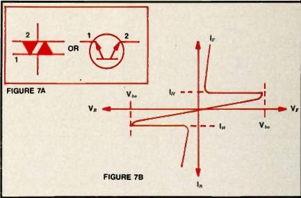
Figure 7. Some SCR gate triggering circuits feature diacs (Figure 7a) for
more positive, ac curate control of the thyristor's firing point. When a voltage
of either polarity is applied across the multilayered semiconductor device,
only a negligible amount of leakage current flows, as long as the potential
difference doesn't reach the breakover voltage NJ. When voltage reaches k(„„
avalanche occurs. Current then flows easily through the device. To turn off
the diac, the current must be reduced below the minimum holding value (lH),
shown in Figure 7b.
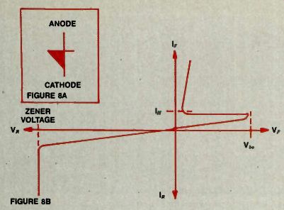
Figure 8. The Shockley diode is a unidirectional PNPN 2-terminal thyristor.
When the applied voltage makes the anode positive in relation to the cathode,
the diode remains essentially an open switch - even though forward-biased
-- until V,, is reached. Then the anode to-cathode voltage suddenly drops
as current begins flowing through the device; it thus enters the forward conduction
region.
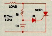
Figure 9. Sharper control of SCR triggering is achieved with a Shockley diode.
D1 re mains in the blocking state until the C1 voltage is high enough to
reach V 6 „. The capacitor's charging rate is determined by the R1-C1 time
constant. When V. is reached, the diode switches on, allowing a rush of current
that fires the SCR, energizing the load.
For example, in Figure 5a, a relatively high amplitude of gate current causes the triggering level (I i,) to be reached early in the positive alternation (at time t1); i.e., at a phase angle of about 15°. This results in about 165° of conduction in each cycle and a fairly high value of average load current.
In Figure 5b. the amplitude of gate current has been substantially reduced by increasing the resistance of R2. Consequently, the gate current doesn't reach the triggering level until time t2. This results in a firing angle of about 75° (conduction angle of 105°) and a lower value of average load current.
To sum up the operation of the circuit in Figure 4, the power in the load is controlled by varying the resistance of R2. Diode D1 serves the same purpose as in Figure 1: It prevents the negative alternation of input voltage from reaching the gate of the SCR. That is why no negative alternations of gate cur rent are shown in Figure 5.
Adding an R-C phase-shift network
The circuit in Figure 4 has a draw back: The SCR's firing angle cannot be increased beyond 90°. As a result, the conduction angle cannot be reduced be low 90°. That problem can be solved by the addition of an R-C phase shift circuit, which can provide up to 90° of additional phase delay. The circuit is shown in Figure 6. Here C1 charges through R1; this takes a certain amount of time, delaying the triggering of the SCR. By increasing the resistance of R1, we can increase the firing angle up to a maximum of 180°, at which point the thyristor remains off and no current flows through the load. Reducing the resistance of R1 shortens the time constant of the R-C network, allowing C1 to charge more rapidly, thus triggering the SCR earlier in the positive alternation of input voltage. This increases the SCR's conduction angle and power in the load.
Diacs and Shockley diodes Instead of the circuitry shown in Figures 1, 4 and 6, some SCR gate triggering circuits feature discs, Shockley diodes or UJTs for more positive, ac curate control of the thyristor's firing point.
-- The Shockley diode is another PNPN 2-terminal thyristor; unlike the diac, however, it is unidirectional--
The diac is a bidirectional thyristor that exhibits negative resistance switching characteristics. It's capable of sup plying sufficient gate current for fast turn-on of SCRs and triacs. A 2 terminal avalanche device, the diac con ducts equally well in either direction when the potential difference across it reaches its forward-breakover or reverse-breakover voltage rating, typically somewhere between 20V and 35V in different diacs. When breakover occurs, the voltage across the device drops sharply as the current through it in creases; hence its negative resistance.
Figure 7 illustrates the diac's symbols and V-I characteristics. When a voltage of either polarity is applied across the multilayered semiconductor device, only a negligible amount (microamps) of leakage current flows as long as the potential difference doesn't reach the breakover voltage (V"). When voltage reaches V b „, avalanche occurs. Avalanche is non-destructive as long as the diac's power dissipation rating is not exceeded. Current then flows easily through the device. To turn off the diac, the current must be reduced below the minimum holding value (I,,), shown in Figure 7b.
The Shockley diode is another PNPN 2-terminal thyristor; unlike the diac, however, it is unidirectional. As shown in Figure 8, its characteristic curve in the useful forward-bias region is similar to the right-hand half of Figure 7.
When the applied voltage makes the anode positive in relation to the cathode, the diode remains essentially an open switch - even though forward-biased - until Vb., is reached. Then the anode-to-cathode voltage suddenly drops as cur rent begins flowing through the device; it thus enters the forward conduction region (closed switch). The zener voltage, where reverse avalanche breakdown occurs, is usually much higher than the forward breakover voltage.
SCR controlled by a Shockley diode
Sharper control of SCR triggering is achieved when the ordinary silicon di ode in Figure 6 is replaced by a Shockley diode, as in Figure 9, where D1 re mains in the blocking state until the C1 voltage is high enough to reach V b „. The capacitor's charging rate, of course, is determined by the R1-C1 time constant.
When Vb. is reached, the diode switches on, allowing a rush of current through the gate of the SCR; this current causes the SCR to fire, energizing the load.
Next month we'll take a look at UJT controlled SCR circuitry.
Also see: