The amplifier as a troubleshooting aid--Part III
--S. Miller
Miller is a senior bench technician for a Lancaster, PA., repair company.
The first two parts in this series introduced the Radio Shack mini-amp (catalog number 277-1008C), which can be used to amplify waveforms within the range of 30Hz to 30kHz. The electronics servicer can use the amp as a frequency-selective pre-amp, as a tester for PG and FG pick-up sensors in VCR motor circuits, and for testing audio circuits.
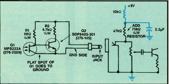
What else can be tested with the mini amp? How about remote control transmitters! You just have to construct a simple pickup probe and add one addition al internal resistor to the modified mini-amp described in the February Video Corner. Figure 1 gives the particulars.
The additional 75 k-o internal resistor is connected between the +9V rail and the center pin of the input jack. This resistor provides a small current through the input cable to power the active pick up probe. This resistor does not affect the other functions of the mini-amp be cause the external input capacitors block this small current when you use the other probes.
Some users of the probe have complained of motorboating when the volume is turned up. Motorboating can be minimized by keeping the volume control turned down. If you wish to eliminate motorboating, modify the circuit as shown by the colored lines in Figure 1.
The active IR probe consists of only four components, all of which are avail able from either Radio Shack or your local parts distributor. The only critical component is Q1, which cannot be substituted. Also note that the collector of Q1 (indicated by a flat spot) goes to ground. Be sure to use several feet of shielded microphone cable to connect the IR probe to the mini-amp.
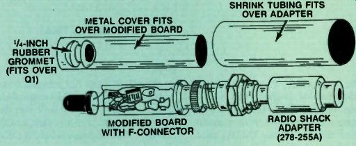
To provide proper shielding, choose a suitable metal housing to enclose the probe. I construct my probes inside discarded 300 ohm to 75 ohm antenna matching transformers. Figure 2 shows the en closure. The transformer's circuit board can be stripped of its components, shortened and used as a construction base for the IR probe. With an adapter, the microphone cable can be easily connected to the transformer's F connector.
After assembling and testing the probe, I fill the pickup end with trans lucent blue RTV silicon adhesive. This RTV protects the pickup and filters out some of the visible light while allow-mg the infrared to pass through. A layer of shrink tubing completes the device.
When using the IR probe, allow 15 to 30 seconds of warm-up for the internal capacitors to charge. Then, with the volume set to maximum, place the pickup near a transmitting remote. If the remote is transmitting data, a tone should be heard from the speaker. The volume can then be adjusted for a comfortable level. Intense visible light will also affect the IR pickup, causing it to either saturate or go into oscillation. Therefore, keep the IR probe away from bright lights while it is in use.
Testing VCR IR LEDs
This IR probe can also be used to test the IR LEDs in VHS VCRs. Other types of IR remote testers cannot provide this feature because they are too bulky to be inserted into the tape department. How ever, my IR probe's pickup is small and attached to a flexible cable, allowing this probe to be inserted right into the VCR. To prevent tape breakage or damage, VHS VCRs detect the ends of the tape spools by using a system consisting of clear tape leaders, a lamp or IR LED, and photo pickup transistors. When a cassette is loaded into the VCR, the IR LED or lamp projects light into the cassette through a hole in the center of the cassette. The opaque videotape normally prevents the light from passing out the sensor windows and activating the photo-transistors. However, at either the beginning or the end of the tape cassette, the light will pass through the clear leader, out the sensor window, and turn on one of the photo-transistors. The system control microprocessor monitors these sensors and prevents tape movement in the direction opposite an illuminated sensor.

Figure 1. To build a remote control transmitter, construct a simple pickup
probe and add the additional internal resistor to the modified mini-amp. To
eliminate motorboating, modify the circuit as shown by the colored lines.
Because of the importance of this safety feature, most microprocessors monitor the condition of the light source and are programmed to inhibit all tape functions if the lamp or LED becomes defective. A typical failure is sensor lamp or LED burn-out. An open sensor LED in a late-model Panasonic ma chine will stop all tape functions. The VCR will load and eject the cassette, but will not allow any tape functions, such as play, fast forward or record. Most other VCRs will also refuse to operate when the lamp or IR LED is defective.
In older machines, the lamp was an in candescent bulb, which could be easily checked by visual inspection. Today, all manufacturers are using IR LEDs, which have an invisible light that makes checking the IR LED more difficult. However, by using the IR probe, you can quickly check these LEDs.
The testing method for IR LEDs varies among manufacturers. Some VCRs are designed to power these IR LEDs with ac pulses; other designs use a constant dc voltage. To check the IR LED, turn the VCR on and place the IR probe close to the IR LED. If a constant tone is heard from the amp's speaker, the LED is functioning and is being driven by an ac waveform. If no tone is heard, wave the IR probe back and forth in front of the LED. If you hear a scratching or popping noise, the LED is functioning and is being driven by a dc supply.

Figure 2. To provide proper shielding, enclose the probe in a suitable metal
housing, such as a discarded 3004 to 754 antenna matching transformer. The
transformer's circuit board can be stripped of its components, shortened and
used as a construction base for the IR probe. With an adapter, the microphone
cable can be easily connected to the transformer's F connector.
A few manufacturers turn on the IR LED only when a cassette is loaded into the machine. To test these machines, load the empty shell cassette into the VCR. (See the April 1989 Video Corner for details on how to construct this device.) Then insert the IR probe through one of the holes in the shell to test the LED. To become acquainted with using the IR probe, test several different models of working VCRs. This experience will be helpful when you are using the device to troubleshoot defective machines.

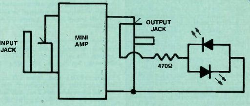
Figure 3. When using the mini-amp to test LEDs, you might find it hard to
hear the sound made by a dc-driven LED as the probe is moved past the LED.
This modification replaces the speaker with LEDs to give a visual, not an
audible, indication.
If all of these IR LED tests have failed, trace the IR LED's wires back to the main board. Next, with the power off, disconnect the IR LED's wires and connect a visible-light LED in its place. If this substitute LED lights and the VCR operates, you have confirmation that the VCR's only problem is a defective IR LED. If the substitute LED fails to light, try reversing it. If it still fails to light, troubleshoot the power supply or LED drive circuit.
Some technicians whose hearing is slightly impaired have complained that when they use the mini-amp to test LEDs, they can't hear the sound made by a dc-driven LED as the probe is moved past the LED. The modification shown in Figure 3 replaces the speaker with LEDs to give a visual, not an audible, indication. With this modification, when the probe is moved past the LED being tested in one direction, one of the output LEDs will light. When the probe is moved in the opposite direction, the other output LED will light.
As we have seen, this mini-amp can be a useful troubleshooting device. Although I have not tried it, I think the IR probe also can be used to check for IR light output from the IR lasers in CD players. Give it a try. It has helped me with countless troubleshooting jobs.