By Joseph J. Carr, CET.
In his seventh and final installment, Mr. Carr describes the theory and operation of the most common digital counting circuit configurations.
A digital counter is a device or circuit that operates as a frequency divider. The most basic form of digital counter is the JK flip-flop connected with the J and K tied HIGH. This makes the output produce one output pulse for every two input pulses. It is, then, a binary, or divide-by-two counter.
ET/D readers are familiar with digital frequency counters. These are simply test instruments that are used to measure frequency. Those instruments contain decade counters (i.e. divide-by-10).
There are two basic classes of digital counter circuits, serial and parallel. The serial counters are called ripple counters because a change in the input must ripple through all stages of the counter to its proper point. Parallel counters are called synchronous counters.
In a ripple counter, the data is transferred serially, which means that the output of one stage becomes the input of the following stage.
The basic element in most counters is the J-K flip-flop (Fig. 1A). Note in the figure that the J and K inputs are tied HIGH, so they will remain active.
A timing diagram for this divide by two circuit is shown in Fig. 1B, and it shows the action of the circuit. J-K outputs change state on negative-going transitions of the clock pulse. In Fig. 1B, the first negative-going transition causes the Q output to go HIGH. Q will remain HIGH until the input sees another negative-going clock pulse. At that time the output will drop LOW. The action required to make a complete output pulse requires two clock pulses, so this J-K flip-flop is dividing the input frequency by two.
We can make a binary ripple counter by cascading two or more stages, as shown in Fig 2A. This particular circuit uses four J-K FFs in cascade. Any number, however, could be used.
The major problem with this type of counter is that only those division ratios that are powers of two can be accommodated. In the four stage circuit shown, the possible division ratios are 2, 4, 8 or 16.
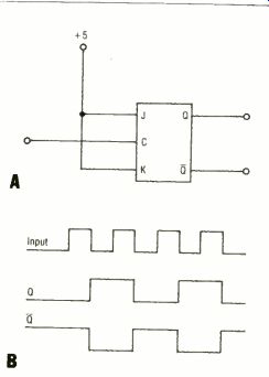
Fig. 1---The J-K flip flop is the basic element in most counters. Figure 1B
is the timing diagram for the circuit illustrated in 1A.
Frequency division is one major use for a counter circuit. In some electronic instruments, for example, we may want to pre-scale a frequency, i.e. divide it from some higher frequency to a lower frequency that can be handled by a digital counter or other instrument.
But this is only one application for the counter circuit. One of the most common applications, alluded to in the last paragraph, is to count, i.e. tell us the total number of pulses that passed.
Consider again the circuit of Fig. 2A, and the timing diagram of Fig. 2B. Outputs A, B, C and D are coded in binary, with A being the least significant bit and D being the most significant bit. These are weighted in a 1-2-4-8 code system to represent decimal, or hexadecimal, digits 0-15. These are the normal weights of the binary number system.
Consider the timing diagram of Fig. 2B. Note that all Q output changes occur following the arrival of each pulse. After pulse number one has passed, the QA line is HIGH and all others are LOW.
This means that the binary word on the output lines is 00012 (i.e. 110); one pulse has passed.
Following pulse no. 2 we would expect 00102 (i.e. 2,0) because two pulses have passed. Note that C)B is HIGH and all others are LOW. The digital word is, indeed, 00102. If you follow each pulse, you will find the binary code to be as shown in Table 1.
The counter shown in Fig. 2A could be called a "modulo-16" counter, a "base-16" counter, or a "hexadecimal" counter. (All meaning the same thing.) The output of a hexadecimal counter can be decoded to drive a display device that indicates 0-9 (decimal) or 0-F (Hexadecimal). In most applications where a person is to read the output, however, a decimal counter is used.
Decimal counters
A decimal counter operates in the base-10, or decimal, number system.
The most significant bit of a decimal counter produces one output pulse for every ten input pulses. Decimal counters are also sometimes called decade counters. The decimal counter forms the basis for digital event, period, and frequency counters. Thus, the hexadecimal counter in Fig. 2A is not suitable for decimal counting, unless it is modified for base-10 operation.
Fig. 3A shows a TTL hex counter modified by adding a single 7400 TTL NAND gate. Recall that a TTL J-K flip-flop uses inverted inputs for the clear and set functions. As long as the clear input remains HIGH, the flip-flop will function normally. But when the clear input is momentarily brought LOW, then the Q output of the flip-flop goes LOW.
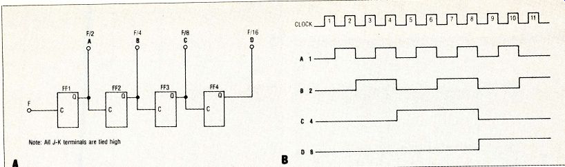
Fig. 2 Cascading four J-K flip flops as in 2A produces this divide by 16 counter,
the timing diagram of which is shown in 2B.
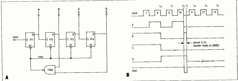
Fig. 3 Figure 3A shows the divide by 16 counter of figure 2A modified with
a standard 7400 NAND gate to function as a decade counter. Figure 3B shows
the timing diagram for the eighth, ninth, and 10th pulses.
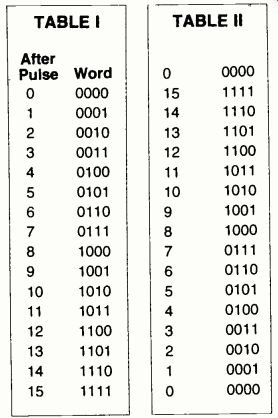
TABLE I
TABLE II
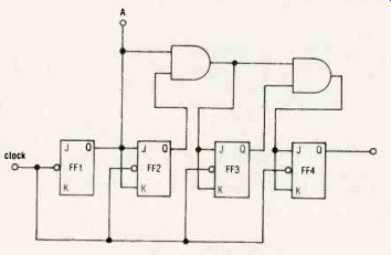
Fig. 4 The basic diagram for a parallel counter-four flip-flops plus two NAND
gates.
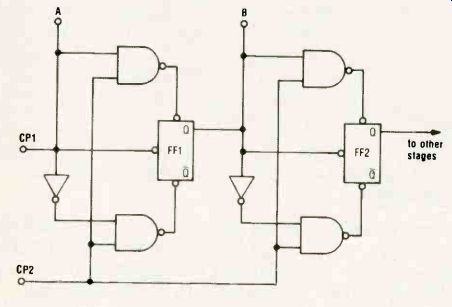
Fig. 5 Two stages of a preset counter using "jam input.
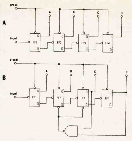
Fig. 6 Two versions of the "down" counter, hexadecimal and decimal.
In 6B a NAND gate "reduces" the count to nine after the eighth pulse.
Note outputs taken from Q while signal inputs are from Q.
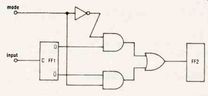
Fig. 7 An inverter circuit, Pius three NAND gates, change this typical cascade
counter into either an "up" or a "down" counter, depending
on the state of the mode input.
How it works
The decade counter in Fig. 3A is connected so that all four clear inputs are tied together to form a common clear. This line is connected to the output of a TTL NAND gate (i.e. one section of a 7400 device). Recall the rules of operation for the TTL NAND gate: if either input goes LOW, the output goes HIGH. But if both inputs are HIGH, then the output goes LOW.
The idea behind the circuit of Fig. 3A is to clear the counter to 0000 following the 10th input pulse. Let's examine the timing diagram in Fig. 3B to see if the circuit does the correct thing. Up until the 10th pulse, this diagram is the same as for the base-16 counter discussed previously.
The output of the NAND gate will keep the clear line HIGH for all counts through 10. The inputs of this gate are connected to the B and D lines. The D line stays LOW (forcing clear to stay HIGH) up until the eighth input pulse has passed.
At that time (i.e. T. in Fig 3B), D will go HIGH, bit B drops LOW. We still have at least one input of the NAND gate (line B) LOW, so the clear line remains HIGH.
The clear line remains HIGH until the end of the 10th input pulse. At that point (T2) both B and D are HIGH, so the NAND gate output goes LOW, clearing all four flip-flops (i.e. forcing them to go to the state where all 0 outputs are LOW). The counter is now considered reset to 0000.
The reset counter produces a 0000, so both B and D are now LOW, forcing the clear line HIGH again. The entire reset cycle occurs during period (T3-T2).
This period has been expanded greatly for graphics purposes in Fig. 3B. In actuality, the reset cycle takes place in nanoseconds or microseconds.
The 11th pulse will increment the counter one time, so the output will indicate 00012. This counter, then, counts in the sequence 0-1-2-3-4-5-6-7-8-9-0-1 . . . The output code is a ten digit version of four-bit binary (hex), and is called binary coded decimal (BCD).
Synchronous counters Ripple counters suffer from one major problem: speed. The counter elements are wired in cascade, so an input pulse must ripple through the entire chain before it affects the output. A synchronous counter feeds the clock inputs of all flip-flops in parallel. This results in a much faster circuit.
Fig. 4 shows the partial schematic for a synchronous binary counter. We accomplish synchronous operation by using four flip-flops, with their clock inputs tied together, and a pair of AND gates.
One AND gate is connected so that both Q1 and Q2 are HIGH before FF3 is active. Similarly, Q2 and Q3 must be HIGH before FF4 is made active. On a clock pulse, any of the four flip-flops scheduled to change will do so simultaneously.
Synchronous counters attain faster speeds, although ripple counters seem to predominate in most applications.
Preset counters
A preset counter increments from a preset point instead of 00002. For example, suppose we wanted to count from 510 (01012). We could preset the counter to 01012, and increment from there. The count would be as in Table III.
Fig 5 shows a common method for achieving preset conditions: the jam input. Only two stages are shown here, but adding two additional stages will make it a four-bit counter. Of course, any number of stages may be cascaded to form an N-bit preset counter.
In fig. 5, the preset count is applied to A and B, and both bits will be entered simultaneously when clock line CP2 is brought HIGH. Line CP2 is sometimes called the enter, or jam, terminal.
Once the preset bit pattern is entered, the counter will increment from these with transitions of clock line CP1.
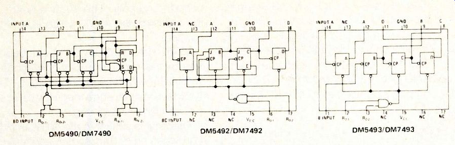
Fig. 8 The three basic counters in the TTL line.
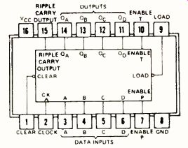
Fig. 9 Pinouts for the TTL series 74160-74163.
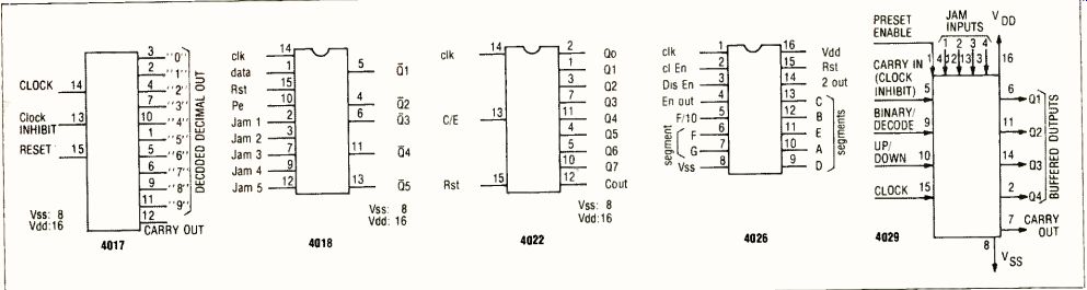
Fig. 10 The pinouts for several popular CMOS counters.
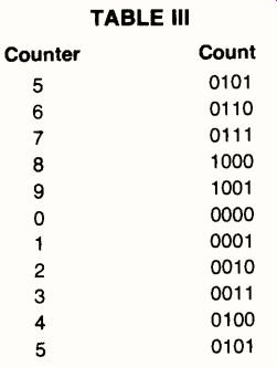
TABLE Ill
Down counters
A down counter decrements, instead of incrementing, the count for each excursion of the input pulse. If the reset condition is 00002, then the next count will be (0000-1), or 1111. It would have been 0001 in an up counter. The count sequence for a four-bit down counter is shown in Table II.
We use basically the same circuit as before, but toggle each flip-flop from the (not-Q) of the preceding flip-flop. An example of a four-bit binary down counter is shown in Fig. 6A. Note that the outputs are taken from the Q outputs of the flip-flops, but toggling is from the Q.
The preset inputs of the flip-flops are connected together to provide a means to preset the counter to its initial (i.e. 11112) state. This counter is also called a subtraction counter, because each input pulse causes the output to decrement by one bit.
A decade version of this circuit is shown in Fig. 6B. As in the case of the regular decade counter, a NAND gate is added to the circuit to reset the counter following the 10th count. We detect the states when C and D are HIGH, and then clear the two middle flip-flops. This action forces the output to 10012 (910).
The counter then decrements from 10012 in the sequence 9-8-7-6-5-4-3-2-1-0-9. Simple, huh!
Up-down counters
Some counters will operate in both up and down modes, depending upon the logic level applied to a mode input. Fig. 7 shows a representative circuit, in which the first two stages of a cascade counter are modified by the addition of several gates. If the mode input is HIGH, then the circuit is an up counter. But if it is LOW, then the circuit is a down counter.
TTL/CMOS examples
Very few digital circuit designers construct counters from individual flip-flops; there are too many "ready-built" IC counters available in all of the major logic families.
There are three basic counters available in the TTL line: 7490, 7492, and 7493 (see Fig. 8). The 7490 is a decade counter, the 7492 a divide-by-12 (also called modulo-12) counter, and the 7493 is a binary (divide-by-16) counter.
All three of these counters are of similar construction, and their respective pin-outs are shown in Fig. 8.
The 7490 is a bi-quinary counter, meaning that it contains a single, independent, divide-by-2 stage, followed by a divide-by-5 stage. Decade counting is accomplished by cascading the two sections.
Both 7492 and 7493 follow similar layout schemes. In both, the first stage is a single divide-by-2 flip-flop, followed by a) divide-by-6 (7492), or b) divide-by-8 (7493). These form divide-by-12 and divide-by-16 counters, respectively.
The 74142 is a special function TTL IC containing a divide-by-10 counter (BCD), a four-bit latch circuit, and a display decoder suitable for driving a Nixie® tube. The 74142 is housed in a standard 16-pin DIP package.
Fig. 9 shows the pin-outs for the TTL types 74160--74163. These are BCD and
binary four-bit synchronous counters:
74160- Decade (BCD) synchronous (parallel) direct clear 74161- Binary, synchronous, direct clear 74162- Decade, fully synchronous 74163- Binary, fully synchronous These counters operate to 32 MHz (typically) and dissipate approximately 325 milliwatts. All are housed in 16-pin DIP packages.
These four counters are different from those that we have seen previously, because they are "divide-by-N" counters (where N is an integer). The value "N" is applied to the Data inputs, and is loaded into the counter when the load terminal is momentarily brought LOW.
Examples of basic CMOS counters are shown in Fig. 10. Again, these examples are not exhaustive, merely representative of those commonly used. None of them are multi-digit decimal counters such as the eight digit, 10 MHz, intersil device.
4017. This device is a fully synchronous decade counter, but the outputs are decoded 1-of-10. The active output is HIGH, while the inactive outputs are LOW.
The 4017 is positive edge triggered.
The reset and enable inputs are normally held LOW. If the reset is momentarily brought HIGH, the counter goes immediately to the zero state. The enable input is used to inhibit the count; that is, if made HIGH the count ceases, and the output remains in its present state.
The output terminal produces a pulse chain of Fin/10; which is HIGH for 0, 1, 2, 3 and 4, and LOW for 5, 6, 7, 8 and 9.
4018. This device is a synchronous divide-by-N counter, where N is an integer of the set 2, 3, 4, 5, 6, 7, 8, 9 and 10. It is difficult to decode the outputs of this counter, so its principle use is in frequency division.
For normal operation, the reset and load inputs must be held LOW. The 4018 is positive-edge triggered.
N Connect Input Pin No. (pin 1) To 2 Q1 5 4 02 4 6 Q3 6 8 04 11 10 Q5 13
The N-code for determining the division ratio is set by connecting the input terminal to an appropriate output, or (in certain cases) an external AND gate. For even division ratios, no external gate is needed. Merely connect the input terminal as shown at left.
The odd division ratios (i.e. 3, 5, 7, 9) require an external two-input AND gate.
The 4018 outputs are connected to the AND gate inputs, and the AND gate output is connected to the 4018 input (pin 1):
N 3 5 7 9
Connect To AND Gate Inputs Q1,Q2 Q2,Q3
Q3,Q4
04,05 Pin No.
5,4 4,6 6,11 11,13
The feedback line described in the paragraph above is also the main output from the counter. If, for example, we connect "input" pin no. 1 to Q3 (pin no. 6), then the pulse appearing on pin no. 1 will be (by the table above) 1/6 of the clock frequency.
We may also parallel load the 4018 using the jam terminals, P1-P5. These terminals will program the 4018. A LOW on a jam input, forces the related Q output HIGH, and vice-versa. For example, if a LOW is applied to P2, it will force Q2 HIGH.
4022. This device is an octal (i.e. divide-by-8) counter that provides 1-of-8 decoded outputs. The 4022 is nearly the same as the 4017, which is a decade.
4026. The 4026 device is a decade counter that produces uniquely decoded outputs for seven segment displays. The 4026 is a positive edge triggered device, and is fully synchronous.
This chip is similar to the 4017, in that it provides an F/10 output in addition to the seven-segment decoded outputs.
The decoded outputs are HIGH active.
There are two enable inputs. One is a clock enable, which will cause the count to cease when brought HIGH. The counter remains in its present state when the clock is inhibited. The other enable terminal is a display enable. A HIGH on this input will turn the display on, and a LOW will turn the display off.
4029. The 4029 is an up-down counter that will divide by either ten, or sixteen, depending upon whether pin no. 9 is HIGH or LOW. A HIGH on pin no. 9 causes the 4029 to be a base-16 counter (binary), while a LOW causes it to be a base-10 (decade) counter.
The count direction (i.e. up/down) is determined by the level applied to mode pin no. 10. If pin no. 10 is HIGH, then the 4029 operates as an up counter. But if pin no. 10 is LOW, then it operates as a down counter.
(source: Electronic Technician/Dealer, Nov. 1979)