How did you do on the last two quizzes? Here's another to test your memory and knowledge on amplifiers, ac, and other things you haven't thought of lately.
by Frank R. Egner, CET.
If you have worked the electronic quizzes in previous issues of ETD, you've probable discovered that you have become rusty in some areas of electronic fundamentals. But don't be discouraged. Most technicians find that they become rusty in many areas over a period of time. If you make a true effort to answer the quiz, and then look up the solutions in text references for questions missed, you'll be surprised at how it will refresh your previous knowledge.
If you are not yet a Certified Electronic Technician, why not use some of your spare time to review and study your electronic fundamentals to get ready for the CET exam? You'll be proud to be a CET because it is evidence of your electronic knowledge and ability. It is hoped that these electronic quizzes will help you get ready for the test. If you'd like further information on the CET program, contact ISCET or ETA-I. The addresses have been in ET/D quite regularly. Also do not forget that NATESA has its own consumer electronics oriented certification program.
This quiz is similar to previous quizzes and is intended to provide a thought-provoking review of electronic concepts. Some questions may seem easy and others more difficult, but none are intended to be "trick" questions. The answers are available to check your solution, but shouldn't be looked at until you've made your best effort on the quiz.
1. The power factor (pf) of an ac circuit is equal to:
a. The sine of reactance divided by resistance.
b. Real power minus reactive power
c. The cosine of the phase angle.
d. Voltage times current divided by reactance.
2. An ac circuit has an applied voltage of 75 volts, a current of 50 milliamps, and a power factor (pf) of 0.85. The power being dissipated is approximately:
a. 3.75 watts.
b. 31.9 watts.
c. 3.2 watts.
d. 0.32 watts
3. An ac voltmeter measures the line voltage at 115vac. The ac average voltage is:
a. 0 v.
b. 103.5v.
c. 115v.
d. 161v.
4. Moving the plates of a capacitor closer together will:
a. Decrease its reactance.
b. Decrease its capacitance.
c. Increase its ac op position.
d. Increase its breakdown voltage.
5. Amplifier gain decreases to half power at high frequencies because:
a. Coupling capacitors have too little capacitance.
b. The reactance of the shunt capacitance decreases.
c. The reactance of the series inductance decreases.
d. By-pass capacitors are too low in value.
6 A tuned circuit in a radio receiver uses an inductor with a movable powdered-iron core. Turning the core further into the coil will:
a. Lower the inductance.
b. Raise the resonant frequency.
c. Reduce its reactance.
d. Decrease the frequency of resonance.
7. The input impedance of a common emitter transistor amplifier:
a. Varies inversely to transistor current.
b Decreases as transistor current decreases.
c Is constant for each type transistor.
d. Increases proportionally as current increases.
8. A zener diode is connected as a shunt regulator. Under this condition:
a. Zener resistance decreases as input voltage decreases.
b. Zener current varies directly as load current varies.
c. Zener resistance increases as load current increases.
d. Zener resistance is constant at its rated voltage.
9. Signal inversion between input and output is a normal condition for which transistor configuration?
a. Common emitter amplifier.
b. Common base amplifier.
c. Common collector amplifier.
d. More than one but not all of the above.
10. At what frequency will the reactance of a 0.01 microfarad capacitor be equal to a resistor of 10K ohms?
a. 160 KHz (Approx).
b. 16 KHz (Approx).
c. 1.6 KHz (Approx).
d. None of these 11. A series-resonant circuit is connected in parallel with a load.
The circuit will function as a:
a. Low-pass filter.
b. High-pass fitter.
c. Band-pass filter.
d. Band-stop filter.
12. A 2KHz squarewave is applied to an RC coupling circuit in which R 10K and C 0.001 microfarads.
The output waveform, if taken across R, will be:
a. A squarewave with minimum distortion.
b. A distorted rectangular waveform.
c. A differentiated waveform.
d. Shifted in phase by nearly 90 degrees.
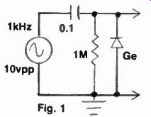
13. The output of the circuit in figure 1, as measured with an oscilloscope on dc input will be:
a. Positive half cycles only, about 5 volts peak.
b Negative half cycles only, about 5 volts peak.
c A full sinewave, centered on 5 volts dc.
d. A full sinewave, centered on 5 volts dc.
14 The circuit of figure 1 could be identified as a:
a. Negative dc restorer circuit.
b. Positive clamper to a zero volt level.
c. Shunt positive limiter.
d. Shunt negative limiter.
15. The transistor amplifier configuration that provides no current gain is the:
a. Common base amplifier.
b. Emitter follower amplifier.
c. Common emitter amplifier.
d. Common collector amplifier.
16. A series resistance-inductance (RL) circuit has an output taken across the resistor. This circuit could be used as a:
a. Low-pass filter.
b. High-pass filter.
c. Band-pass filter.
d. Band-stop filter.
17. Kirchhoff's voltage law states that in all circuits:
a. The algebraic sum of all voltage drops and rises is equal to zero.
b. The algebraic sum of all loop voltages equals zero.
c. Both a and b are true.
d. Neither a nor b is true.
18. The dc input of a calibrated oscilloscope has an impedance of 1 megohm, shunted by 35 picofarads.
The scope is connected across one of two series connected 500K ohm resistors across a 20 volt dc source.
Using the 2v, div range, the trace will deflect about:
a. 4 divisions.
b. 5 divisions.
c. 4.5 divisions.
d. 3.6 divisions.
19. An iron-core transformer, having a 1:1 turns-ratio, would most likely be used for:
a. Impedance matching.
b. Voltage regulation.
c. Safety precautions.
d. Current regulation.
20. In figure 2, the most likely indication of a shorted capacitor CE would be:
a. An excessive amount of gain.
b. A decrease in voltage gain.
c. An improvement in signal linearity.
d. Increased amplifier bandwidth.
21. In figure 2, the most likely indication of a shorted capacitor CE would be:
a. A change in the 01 operating point.
b A complete loss of voltage gain.
c. An improvement in signal linearity.
d. A decrease in amplifier bandwidth.
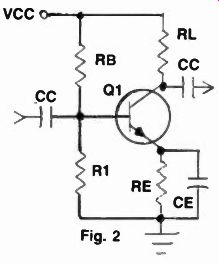
------ Fig. 2
22. In figure 2 the input and output signals are in phase. This could be an indication that:
a. Q1 is shorted E to B.
b. Q1 is shorted C to E.
c. Q1 is shorted B to C.
d. This is normal for this configuration.
23. In the circuit of figure 3, increasing the generator frequency will:
a. Decrease the resistor voltage.
b. Decrease the circuit phase single.
c. Increase the power dissipation.
d. Reduce the inductor voltage.
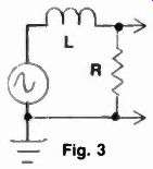
------ Fig. 3
24. In figure 3 the generator frequency is such that reactance and resistance are equal. Then:
a. The phase angle is 45 degrees.
b. Inductor voltage plus resistor voltage is greater than the generator voltage.
c The inductor current is greater than resistor current.
d More than one but not all the above are correct.
25. In figure 3, inserting an iron core in the coil will:
a. Decrease the inductor voltage.
b. Increase the resistor voltage.
c. Decrease the power dissipation.
d. Increase the circuit current.
Electronic quiz solution
1. c 6. d 11. d 16. a 21. c
2. c 7. a 12. c 17. b 22. c
3. b 8. c 13. d 18. a 23. a
4. a 9. a 14. b 19. c 24. d
5. b 10. c 15. a 20. a 25. c
You should have missed no more than 6 questions to make 75%. If you missed more, you could use some reviewing of electronic fundamentals.
(source: Electronic Technician/Dealer)