Basic to your ability to sell and install security systems is an understanding of overall system design. You must set up an adequate, perhaps expandable, system for a reasonable price. Here's a concrete design example.
by James A. Ross * [At the outset, I wish to give thanks to Robert T. Kroll, a friend and former student at Capitol Institute of Technology. Bob assisted with the development of the Electronic Security Seminar at Capitol Tech by using various donated equipment in the design of the system which is described in this article. Thanks to his talents and hard work the college has a working model of a modern intrusion and fire alarm system. ]
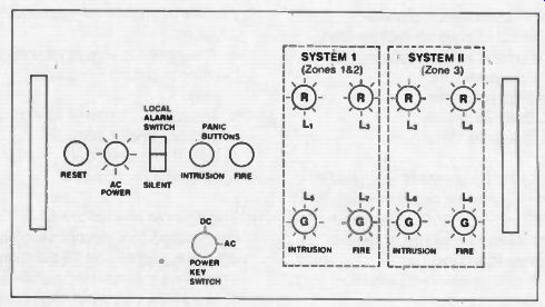
Fig. 1: Master Control Panel
The first step in any design problem is to determine what is to be accomplished. (I know that this sounds silly because it is so obvious, but I have seen countless examples of waste in government programs due to the failure to specify real, necessary goals at the outset.) In this case our principal goal was the development of a demonstration model of an intrusion and fire alarm system for use as an instructional aid. We determined that desirable features of our system were:
1. Several zones for intrusion detection.
2. Smoke and heat sensors
3. Master control panel with status indicator lights.
4. Local alarms for intrusion and fire.
5. Remote alarms via telephone dialer for intrusion and fire.
6. Backup power in case of loss of AC.
Also, because it is a demonstration system intended to be used as an instructional aid, it should be mounted in an enclosure which can be wheeled from storage into the classroom as needed. As far as possible, components which are to be demonstrated should be located high enough so that they can be seen from the back rows of the classroom.
As in any design problem, after listing the goals, it is necessary to take stock of what resources we have available, and constraints which might cause us to modify our goals. In this case we had the following equipment available:
Rockland model 515 Residential Panel Rockland model 562 Commercial Panel Rockland model 500 Telephone Dialer Ademco model 632D Smoke Detector Heat Sensor Magnetic Switches Dialer Programmer Solid State Siren Buzzer
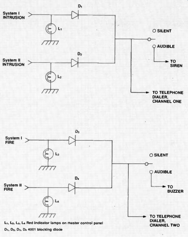
Figure 2. Interconnect Circuitry
In addition to the hardware listed, and far more important, we had the capabilities of the designer, Bob Kroll, who combines theoretical knowledge with practical, hands-on experience.
The single most important constraint was the budget--the entire project was limited to $50 of new expenditures. Because of a shortage of classroom space in the school, we were forced to design a portable system which meant that a large part of the budget had to be used for lumber, hinges, etc. leaving very little for wiring, battery, master panel, status indicator lights, etc.
Equipment Characteristics
In the demonstration unit the master control panel is located at the top front for maximum visibility in the classroom; however, in an actual installation this panel would be located in the security office. Keep in mind that this panel is one which we added because we wished to demonstrate a greater capability than that of either the 515 residential panel or the 562 commercial panel. Also, we wanted to demonstrate that it is possible to combine commercially available units using simple binary logic circuits made of inexpensive components. A drawing of the face of the master control panel is shown in Figure 1. The reset switch controls the smoke detector and intrusion circuits of the 515 residential panel. The lamp marked "AC Power" glows when ac power is available for use whether the unit is being powered by either ac or dc. The silent alarm switch disconnects the heat and smoke buzzer and the intrusion alarm siren. With these disconnected, fire or intrusion would activate the appropriate channel of the dialer, but there would be no local alarm sounded. The panic buttons on the master control panel will activate the intrusion alarm or the fire alarm.
Again, control over the local alarms is maintained by the local alarm switch.
If it is in the silent position, the appropriate channel of the dialer will be activated by the panic button, but no local alarm will sound.
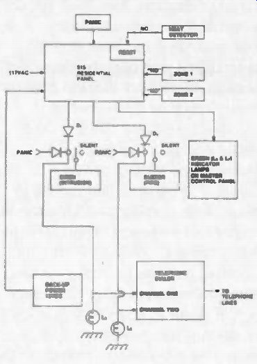
Figure 3 System 1
The status indicator lights are located on the right side of the master control panel. The lower lights are green and indicate which systems are activated, and operating properly. The red lights on the upper level indicate an alarm condition. The intrusion circuit for zones 1 and 2 can be reset by the reset button on the master control panel, but System II must be reset within the 562 control panel because it has no provision for remote reset.
Also, if any intrusion circuit has been activated by any of the panic buttons, it must be reset within its own control panel (515 for zones 1 and 2 and 562 for zone 3). The smoke detector will reset itself after activation and the heat sensor used had to be replaced after activation.
The 515 residential control panel has provision for input from two zones for intrusion detection and one for heat detection, and the 562 commercial control panel accommodates input for only one zone of intrusion detection and the smoke detector. (The commercial panels are less complex because they are mostly sold to small retail stores which usually have a much simpler layout than a home.) The panels used will accept inputs which are normally open ("NO") or normally closed ("NC"). In our application zones 1 and 2 are "NC", and zone 3 is "NO." The heat and smoke detectors are "NO." The model 500 dialer is a two channel device, providing two different reactions depending on whether it is activated by an intrusion or by smoke/ fire. Channel one of the dialer is activated by an intrusion alarm, and channel two is activated by a fire alarm. This dialer will accept inputs including a dry (no voltage) closure and from 5-12 vdc, depending on the setting of the function switch. One important feature of this dialer is that channel two has automatic priority over channel one so that if a fire occurred during transmission of the intrusion message, the dialer would switch to its channel two response.
Upon activation of channel one intrusion detection, the dialer will dial the first of three programmed telephone numbers (from one to eleven digits) and play the recorded message, then it will dial the second number and play the recorded message, then it will dial the third number and play the recorded message, and turn itself "OFF." Activation of channel two results in dialing those numbers and playing the channel two message. There are, of course, several options which could be added, but one standard feature latches an indicator light "ON" each time the dialer is activated. This tells you, even if you have not been reached by a telephone message, that the dialer had been activated since it was set.
System Operation
This system incorporates two standard panels, one master control panel, a telephone dialer, a buzzer fire alarm, and a siren intrusion alarm. The two standard panels are connected to the master control panel and the alarm system with simple "OR" gates as shown in Figure 2. As you can see, the master control panel indicator lamps will indicate whether System 1 or System 2 has been triggered, but the alarm circuitry will be activated if either System I or System II has been triggered. The block diagram for System 1 is shown in Figure 3 and the block diagram for System II is shown in Figure 4. Note that several panic buttons can be used in the system in addition to the ones shown by connecting them in parallel to the "NO" inputs to System II. The master control panel will indicate which zones are "ON" with green lights L5, L7, L6, and La; and will indicate alarm status with red lights L1, L3, L2, and L4.
Most of the elements of the system can be powered by a wide range of dc voltages so that 24 vdc from the 117 vac power supply is acceptable as well as 12 vdc from the back-up lead acid automobile battery. Only the siren driver might be damaged by higher than 12 v input, so it is protected with a 7812 voltage regulator. No false alarms have ever been generated when changing from ac to dc or from dc to ac.
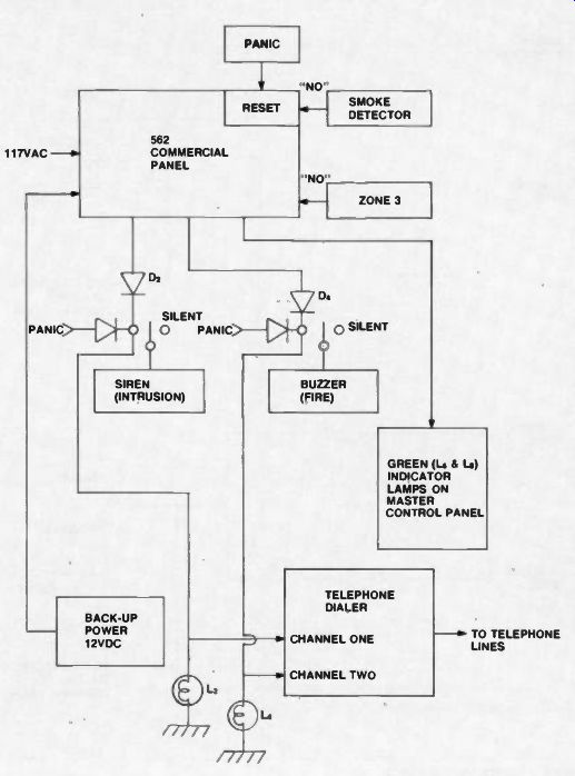
Figure 4 System II
Special Considerations Before connecting to phone lines, you should be familiar with applicable Federal laws and local telephone tariffs. Also, in some areas it is illegal to have a dialer dial the police directly. If the dialer is dialing the owner of a business, the message can be very simple, e.g., "Intruder"; but if a central station is being called, the message will have to include the identity of the firm, and its address as well as the type of emergency. You will probably use the same telephone numbers for both fire and intrusion, but the messages will be different. Also, you should check local laws regarding sirens because in some places you are required to include a timed automatic cutoff.
The system described uses normally closed circuits for zone 1 and zone 2, and a normally open circuit for zone 3.
In a practical application zone 1 and zone 2 might be in the same building with zone 1 an office area open 9-5 and zone 2 a manufacturing area open 7-3. Having different zones allows for activation of one without the other.
Zone 3 obviously could be another building, used only occasionally, so it requires separate circuitry. However, zone 3, with its normally open inputs from sensors might just be something entirely different. Recall that zone 1 and zone 2 are normally closed inputs. That means each one is a string of low-resistance door switches, window tape, break-wire across skylights, etc. Both of these zones are providing perimeter protection only, and the best use of zone 3 might be to provide area protection in both the office area and the manufacturing area. In other words, zone 3 could be both zone 1 and zone 2.
How would this work? Simple. When the last person leaves for the night, he activates zone 3 with inputs from several sensors throughout the building. These sensors will all be connected in parallel at the "NO" input to the 562 panel. (This requires something that installers don't like-a "home run", or conductor pair run from each sensor back to the panel.) The sensors can be point sensors like mat switches, line sensors like infrared beams or trip wires, area sensors like passive infrared motion detectors, or microwave or ultrasonic Doppler motion detectors, or many others.
The advantage of connecting an area protection system as zone 3 is that it will generate an alarm even if the intruder has beaten the perimeter sensing system.
Conclusion
The system described is a very simple one, but I am sure that you can appreciate how complex it must seem to someone who does not work with electronics technology. Friends who work in this field tell me that their biggest problem is to find competent installers. They say that 90% of their service calls are to correct errors made in installation.
If you have any questions about this system or about this technology, please contact me c/o Electronic Technician/Dealer.
(source: Electronic Technician/Dealer)
Also see: Alarm Systems Design and Sources of Supply [Mar. 1981]