Given a certain signal at the antenna, you need to know what preamp you may need, if any, to function with the necessary downlead to result in an adequate signal to noise at the television receiver. Here is a useful nomogram and how to use it.
by James E. Kluge [James Kluge is a technical editor with the Winegard Company]
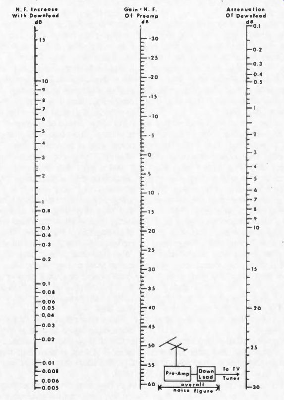
Fig. 1. A Noise Figure/Line Attenuation/Preamp gain, nomograph.
There are times, when calculating the design of an MATV system or even a simple residential antenna installation, that you need to know how to choose the right antenna preamp to go with a given length of downlead cable for the application.
The choice is affected by several considerations, one of which is signal to-noise degradation caused by attenuation in the downlead.
The question that frequently arises is: "With a certain preamp, given its gain and noise figure, how much downlead can I run before I start to degrade the signal-to-noise ratio?" Or, in another case, the downlead may be determined and fixed so that you need to know what preamp gain and noise figure will best preserve the signal-to noise ratio derived from the antenna terminals.
The discussion that follows presumes that the antenna signal is marginal (perceptible snow or graininess in the picture) and that little if any degradation of the received signal can be tolerated.
A preamp becomes necessary to preserve the antenna signal and it must have a low noise figure so as not to degrade further the marginal antenna picture quality.
For example, two basic antenna preamps for VHF and UHF differ by their gain-they are 14-dB and 24-dB gain amplifiers. Their average noise figure at VHF frequencies is 3dB and at UHF may be either 8.5dB or 2.2dB depending on whether you choose the standard or low-noise version. For the purpose of our discussion, let us assume that for UHF we use the low noise preamp and to simplify our calculations we'll consider the noise figure for both the VHF and UHF preamps to be 3dB. Assuming the signal from the antenna to be marginal with respect to noise (i.e. S/N = 30dB), any degradation caused by amplifier noise or attenuation will affect picture quality and may be noticeable. Therefore, it would be useful to know and to be aware of the noise contributing factors and their relative importance.
The nomograph in Fig. 1 offers a quick and easy way to evaluate the effects of down-lead attenuation that results in a degraded signal-to-noise ratio after the amplified signal leaves the antenna preamp.
To use the nomograph, add the noise figure (in dB) to the gain (in dB) of the preamp and locate that point on the center scale. Then, with a straight edge, pivot on this point and read on the left-hand scale the noise figure increase (in dB) and for the amount of downlead attenuation (in dB) read on the right-hand scale.
Example: an antenna preamp has a gain of 14dB and a noise figure of 3dB. Together they total 17dB; locate that point on the center scale. Lay a straight edge on this point and pivot it to intercept the left-hand scale at an arbitrarily chosen 1-dB increase. The straight edge intersects the left-hand scale at 11.1dB attenuation. This shows that a length of downlead, having approximately 11dB of attenuation, connected to the preamp output will produce an overall noise figure (preamp plus downlead) 1 dB higher than that of the preamp alone i.e. NF = 3 + 1 = 4dB. To state it another way, the signal-to-noise ratio at the end of the downlead is 1dB worse than where the signal exits at the preamp.
Different coaxial cables exhibit different rates of attenuation resulting in varying lengths. For example, 11dB i, equivalent to running 230ft. of CL 2700 (RG 59/U type MA N cable with foam dielectric) at channel No. 13 or 115ft. at channel No. 70; if using CL 2800 (RG 6/U type MAN cable with foam dielectric) the above lengths increase to 350ft. and 155ft, respectively.
If you have a fixed run of downlead, and know the cable to be used, you can then go back to the nomograph and either determine the noise-figure increase, or for a given maximum increase determine the gain-plus noise-figure total for the most economical preamplifier in this application.
Note that the noise-figure increase also represents an equal decrease in the signal-to-noise ratio as the signal passed from the preamp output to the other end of the downlead.
In a simple residential or commercial MA N system, the downlead may go directly to the TV set tuner. TV tuners have notoriously poor noise figures that fall in the range of 6 to 8dB at VHF and 12 to 15dB at UHF. Any attenuation ahead of the tuner adds directly to the tuner noise figure. Now, the downlead has significant attenuation but the antenna preamp has gain which when the two are combined, will add up to a net gain or attenuation ahead of the tuner. If it is a net gain, then consider it as an amplifier having that net gain and a combined noise figure computed from the nomograph as in the example above. Then compute the new overall noise figure (preamp + downlead + tuner) by entering the tuner noise figure (in dB) on the right hand scale instead of downlead attenuation. This scale is actually noise figure of a "second stage" which in the case of downlead following a preamp, the downlead is considered the "second stage". Any attenuation in the downlead, or a pad, splitter, or any inserted passive device that adds attenuation (or insertion loss) is equivalent to the noise figure of that portion of the system. Only for convenience was this scale labeled "downlead attenuation". Likewise the center scale can represent any amplifier gain or even a passive device (using the minus portion of the scale where net gain plus NF is less than 0 dB). As an example, a VHF-TV tuner has a noise figure of 10dB and 100ft, of CL-2700 downlead is connected to its input (TV-set antenna terminals). CL-2700 attenuation is 2.3dB per 100ft.
In this case, the downlead becomes the first portion of the combination and the tuner becomes the second. The downlead "gain" (-3.2dB) is added to its noise figure (3.2dB) to equal "0"dB. (This will hold true for any passive device or section, i.e. 0 dB) Find 0 dB on the center scale and 10dB on the right hand scale of the nomograph and lay a straight edge through these two points. Now read"10db" on the left hand scale and add it to the "noise figure" of the downlead to equal 13.2dB for the noise figure of the downlead plus the TV tuner.
Note that it was unnecessary to use the nomograph! As mentioned previously, simply add any attenuation immediately ahead of the amplifier to the amplifier noise figure to compute the combined noise figure.
Now, let's go one step further and add a preamp ahead of the downlead and compute the overall system figure from antenna (antennas have 0-dB noise figure) through the TV set tuner.
Enter preamp gain + preamp noise equals 17dB on the center scale and 13.2dB (NF of downlead + TV tuner) on the right hand scale. Read 1.6dB increase on left-hand scale. Thus, the overall system noise figure equals 3dB (preamp NF) + 1.6dB = 4.6dB. Note how adding a low-noise-figure preamp at the antenna improves the overall noise figure from 13.2dB to 4.6dB. With an 8.6dB improvement in signal-to noise, a grainy, snowy picture should readily clear up by adding a low-noise preamp.
Note also that any reduction in preamp noise figure adds directly to the signal-to-noise ratio of the picture on the screen.
It may appear at first glance that an amplifier having a high noise figure will be compensated by its low gain (because the sum of these two are entered on the center scale); or, that a high noise figure and a high gain together provides a smaller overall noise-figure increase (which is true only because you started with a poor noise figure, high gain or both). The question is: "Can you afford to use a preamp with a poor noise figure at a point in the system where the system noise figure, to be established, depends almost entirely on the preamp noise figure?" I think you'll find the answer to be "No"! High gain will reduce the NF increase but never try to compensate for a poor noise figure with higher gain.
Whether a high-gain preamp is chosen should depend on 1) how much you can reduce the NF increase versus the additional cost of more gain, and 2) whether the reduced total input capability of a high-gain amplifier will cause overload. These choices must be carefully weighed and considered.
(source: Electronic Technician/Dealer)
Also see: