A logical step-by-step procedure for designing a security system can save time and eliminate uncertainty as to system effectiveness. It can also spell out to the customer and the designer the capabilities of the system. Here is a more or less universal process for such design.
by James A. Ross* and Steven Browne** [• Capital Security and Surveillance Systems, Inc., Washington, DC; •• Solid State Electronics, Rockville, MD ]
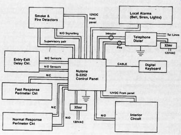
Fig. 1. Interconnections of controls, sensors and alarm circuits to the control
panel.
The first, last, and most important guiding rule for effective design is: "KISS" Keep /t Simple, Stupid.
Always keeping "KISS" in mind the design process logically proceeds through four steps:
1) Determination of what you intend to accomplish,
2) Evaluation of any special considerations which might cause modification of 1),
3) Assessment of the capabilities of your enemy, and
4) Assessment of the resources that you can bring to bear on the problem.
In a practical situation, you might work through these four steps several times because steps 2), 3), and 4) may well modify the initial statement of step 1). For instance, to point to something recently in the news, the Three Mile Island nuclear power generating plant was intended to convert nuclear energy to electrical energy. However, the overriding special consideration of step 2) should have been: the operation of the plant must never endanger life. If this had been properly evaluated, the plant would not have been built as it was. In our situation, designing a home security system, step 2) will probably be the admonition of the homeowner to design a system that he can live with, e.g., no switch mats where a pet or a midnight-snacking human can trip the interior circuit, etc.
In step 3) you must assess what it is you are protecting, and against whom. If the prize is worth the attention of a professional, then you must create a system which will protect against a knowledgeable attack. If the potential enemy is an impulsive amateur, your design will be much simpler.
Step 4, though, is the one which regularly sends you back to step 1). In this step you advise the homeowner how much it will cost to do everything, and that's when you begin to simplify the system, because most people in the real world have limited resources.
The design which this article will describe is based on many real residential fire/intrusion detection and alarm systems which the authors have designed and installed, without of course, providing any information which could compromise a specific system. For the purposes of this article we'll assume the homeowner has insisted on the most protection with the least inconvenience to family and servants.
Overall home security system
There are an infinite number of ways that a home security system can be configured, but, in a practical sense, all systems consist of four separable circuits: exterior, perimeter, interior, and fire/smoke, connected to one or more control panels. As noted in a previous article in this series, the individual circuits may be broken into zones to provide additional flexibility.
Control panel
The control panel is the heart of any system. It includes the switches for turning elements of the system "ON" and "OFF," the logic circuits which respond to inputs from sensors, panic buttons, key switches or digital keyboards, and the outputs to signaling systems. For this representative residential design we have chosen the Nutone S-2252 panel because it has many features which we wish to incorporate in our design.
Figure 1 is a block diagram of the interconnection of controls, sensors, and alarm circuits with this Nutone panel.
Exterior circuit
Most home systems have no exterior circuit at all, because the threat is not severe enough to justify the heavy expense. If needed, an exterior circuit would probably use a proximity or vibration sensor system associated with a wire fence around the property.
Another excellent exterior sensing system consists of an array of buried microphones. These seismic systems sense the vibrations caused by a person walking and automatically trigger an alarm. At least one type, made by Intrusion Detection Systems (IDS) of San Leandro, California, has a verification mode in which you can listen to the amplified sounds of motion.
Recently Colorado Electro-Optics introduced a product called "Security Light Control" which is intended to be used in conjunction with your front (or back) porch light. The unit would not normally be connected to the security panel, but would operate independently once activated. The unit will sense a person approaching the door in darkness, by the infrared radiation from the person, and turn the porch light "ON". If the person is a friend, he will appreciate your thoughtfulness. If he is a burglar, he will most likely skedaddle.
In our representative design for this article, we are not using a seismic system, but will use a security light control at each of three doors.
Perimeter circuit
This is the circuit which covers all doors and windows, and which would be left "ON" even when the family is home and up and about. In designing the system, however, at least one door will be designated as an "Exit Entry" door. The normally closed switch from this door (or these doors) is wired separately to terminals on the panel which are connected to a time delay circuit, so that the user can enter and leave his home without generating an alarm. The Nutone panel, for one, has an interesting feature in its exit-entry circuitry. The time delay is adjustable for any period up to 45 seconds which means you have that length of time after entering to turn the system "OFF" to prevent sounding the alarm. The Nutone panel helps you to remember this by emitting a gentle buzz from the time the door is opened until the system is deactivated.
Note in Figure 1 that the entry-exit delay circuit contains both normally open and normally closed detectors.
This allows flexibility and simplicity in designing this circuit. For instance, a N/O floor mat could be used inside the front door in the simplest installation. In our design we will use both a floor mat and a recessed plunger switch in this circuit.
The fast response perimeter circuit is used with glass break detectors, which are fastened to each window not otherwise protected. This circuit will provide instant response if any protected window is broken.
The normal response perimeter circuit has been designed by Nutone to help to prevent the annoyance caused by false alarms due to momentary unintentional contact in sensitive detectors. The remainder of our detectors will be connected to this circuit. Note that this circuit also has provision for either N/C or N/O detectors.
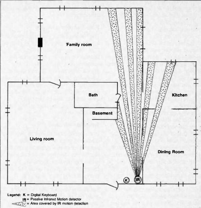
Fig. 2. Partial floor plan showing location of digital keyboard and IR coverage
pattern.
Here we come to the design feature which provides for superior perimeter protection while reducing inconvenience to the minimum, namely alarm screens. If we had used plunger switches or magnetic switches to protect windows, we would have had to also put a shunt switch next to the window so that the window can be opened for ventilation without activating the alarms. That means that the window opening is not protected while the window is open, and, certainly you would not leave home with the window open. Our design uses a special screen which has a conductor unobtrusively woven through it which is connected in series with the N/C perimeter circuit. If the screen is cut, the alarm activates. The screen also includes a magnet which holds a recessed magnetic switch closed as long as the screen is in place. Therefore, removal of the screen will also generate an alarm.
In addition, all doors including the sliding glass doors are protected with recessed plunger switches in the NC perimeter circuit. These switches protect against the intruder who opens the door, but they don't protect against the burglar who breaks the glass and steps through the opening, so we use audio detectors (glass break detectors) in every room with a glass door.
It is very important to keep in mind that all of the detectors described so far are connected in the perimeter circuit. One of the features of this particular panel is the ability to turn "OFF" the interior circuit so that family members can move about freely but still be protected by the perimeter circuit. Considering this, if it is felt that a radio transmitter panic button is necessary, its receiver should be wired into the perimeter circuit so that the transmitted panic signal will activate the alarm even if the interior circuit has been turned "OFF. Also, any other sensor intended to activate the system while the interior circuit is not activated should be connected into the perimeter circuit.
Fire/Smoke circuit
The Nutone panel has no provision for turning this circuit "OFF"; it is always " ON-. As you can see in Figure 1, supervision is included because the sensors are normally open. The smoke detectors should be mounted (on ceiling or high on wall) in bedroom area and at the top of each staircase.
Also available are heat (temperature) detectors and rate-of-rise heat detectors, used to detect a flash fire with little smoke.
Interior circuit
In the previous article in this series we discussed some of the available sensors for interior protection and the reasons for their use. In a residence with a high level of perimeter protection, the interior sensor system does not need to be elaborate.
(Conversely, in a commercial installation where a wall or skylight could be breached or the intruder could hide somewhere inside during the day - interior sensors are extremely important). Figure 2 shows a part of the floor plan of our representative residence, with the location of the controlling digital keyboard and the pattern covered by the passive infrared motion detector. We'll cover the digital keyboard in more detail in the next article, but, for now, it is only necessary to point out that the coverage pattern of the IR sensor has been directed so that the homeowner can activate the interior system by keyboard and then move to the front door without causing an alarm.
Similarly, after returning, he can deactivate the interior system without entering the IR coverage area. Note, though, that the passive IR covers the basement door, and the sliding glass door in the family room. It even provides some protection in the kitchen!
Summary
In this article we presented the general rules of design, and some specifics regarding the design of a residential security system. In the next article we'll discuss the control circuits and signaling systems. As always, questions and comments are welcome.
(source: Electronic Technician/Dealer)
Also see: Intrusion Detectors