Leader's LBO-517 50MHz Oscilloscope -- Quality and Features
By Peter B. Credit
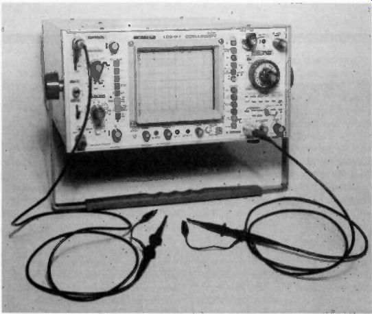
--------- The Leader LBO-517 50MHz oscilloscope.
The LBO-517 from Leader is a 50MHz oscilloscope with the features of a lab grade oscilloscope, one of which is the capability of displaying simultaneously if needed, up to eight traces from four different input signals. The LBO-517's other features include: very comprehensive triggering (which I found to be very stable) due to frequency selective coupling filters, a trigger holdoff control, and an alternate triggering mode that permits measurement and comparison of two signals that are unrelated in frequency.
In addition, the signal providing trigger to the main timebase can be instantly identified and displayed by pressing a pushbutton. Other features include a rectangular CRT with graticule illumination, a calibrated delayed time base which allows for accurate measurements and observations of complex waveforms or long pulse trains, and the capability of displaying the main and delayed timebases simultaneously, resulting in displaying both the complete waveform and the expanded section at the same time.
The specified bandwidth of the LBO 517 is 50MHz at - 3db (it exceeded this in testing) with a rise time of 7 ns.
The vertical deflection factor is 5mv cm to 5v/cm in 10 calibrated steps. A x 5 multiplier adds 1rny cm and 2mv cm steps for frequencies below 10MHz.
The accuracy is ± 3% and ± 5% with the ,< 5 magnification. The input impedance is 1M-O +- 2%, (35pf 3pf) with a maximum input voltage of 600v (dc plus ac peak). The different modes for the timebase generator are, main time base only (TB), main time base intensified by delayed time base. delayed time base, and main time base alternated with delayed time base. The main (A) time base sweep speed is calibrated in 22 steps from 0.05 s cm to 0.5s cm in a 1-2-5 sequence. The B time base is calibrated in 20 steps from 0.05 us cm to 0.1s cm.
There is a x 10 magnifier that extends at any timebase setting the sweep speeds of the main and delayed time bases to 5ns cm. The accuracy of the time base is unmagnified. and 5% magnified. The delay time is continuously variable, a multiplier with 1000 divisions.
The different modes of the main time base triggering are auto, normal, and single shot using ac. dc. LF reject (re moves signal components lower than 5KHz), HF reject (removes signal components higher than 20KHz), TV vertical (a shaping filter whose low frequency output is used for triggering) and TV horizontal.
The delayed time-base triggering sources are internal and external, with an immediate mode (B sweep begins immediately after delay time) and a triggered mode, (B sweep begins after first trigger pulse occurring after delay time). Both the main time base and the delayed time base triggering have a maximum input voltage of 600v (dc plus ac peak). On the rear panel of the LBO 517 there is the CH-1 output control which provides an amplified output of the channel 1 signal which can drive a frequency counter, the CH-3 control which positions the channel 3 (main time base trigger) trace on the CRT, the CH-4 pull quad control which when pulled displays as channels 3 and 4 the signals being used to trigger the main (A) and delayed (B) time bases. provided the alternate or chop push button is also in. Also on the rear panel is the Z-axis input connector which is used to apply signal to intensity modulate the CRT, and the CH-4 external input which is used in applying an external signal to the oscilloscope for delayed (B) time base triggering and display as the channel 4 trace: and the B sweep triggering level control which is used to select the amplitude level at which the sweep is triggered, and the B sweep triggering source switch which selects either internal or external CH-4 trigger signal for the delayed (B) time base.
I thought the quality of construction of the LBO-517 was above average for most imported oscilloscopes of similar type due to its all steel case (which should help in shielding RFI), an aluminum front panel which is bolted to an aluminum sub panel, glass epoxy printed circuit boards and IC's that plug in. The internal layout and construction is very neat and compact also.
Another feature that I like is the abundant use of lighted indicators that indicate "out of calibration," "magnification on," "main time base triggered," "single shot ready," and power on.
Since the maximum input with a X10 probe is 50v/cm (400Vp-p for a full height trace) the X100 probe would be useful and would extend the input capability to 1600V as well as offering an input impedance of 100 megohms in parallel with about 8pf.
The size of the LBO-517 is 11 1/4 x 6 1/4 x 14 3/4 inches and weighs 25 1/2 lbs.
It comes with a full two year warranty and is supplied with two probes and a very complete manual.
(source: Electronic Technician/Dealer)
Also see: Test Instrument Report (April 1981)