[Adapted from the book "Micromatics" by Steven K. Roberts, published by Scelbi Publications, Elm, Ct. ]
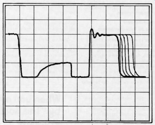
Fig. 1. A scope view of a hypothetical bus line.
To most of the microprocessors while not new is a rather mysterious little black box and we still haven't faced its troubleshooting. Here is a new concept of troubleshooting to apply.
by Steven K. Roberts
Numerous articles in these pages have presented, over the years, a number of observations about microprocessors which suggest some of the fundamental differences between "smart" and "normal" logic.
Not the least of these is the central concept of operation on the basis of a stored program rather than the configuration of the hardware.
This, and the many other aspects of microprocessor-based systems that make them so flexible, results in a real need for a fresh approach to service. Classical debugging and fault isolation techniques are quickly proven inadequate when the attempt to track down a problem with an oscilloscope carries one endlessly in a circle. Assuming some general understanding of microprocessor fundamentals, let's look at the philosophies and tools that are central to their repair.
The job may seem trivial, perhaps, when you consider that most of a system's logic is contained within a relatively small number of complex IC's. Even though this renders invisible the points in the logic which would otherwise be useful as test points, you can always just swap chips, right? The catch here is that the majority of system problems do not involve simple device failure.
System problems, instead, tend to be a little more obscure than that. We can split them into two broad, overlapping categories, which we'll call the "inexplicable crash" and the "consistent hardware problem." The inexplicable crash appears without warning, usually. Perhaps a marginal bus buffer somewhere in the system delivers a "1" instead of a "0" on some bit during an instruction fetch, or perhaps a noise pulse from a nearby air conditioner has the same effect. Maybe an address bit is slow to change and the CPU, for just a few hundred billionths of a second, sees a memory location other than the one which was intended. Suddenly, unpredictable events start to occur with extreme rapidity: instead of, say, a "Decrement Register B" instruction, the processor may see, for whatever reason, a CALL to some location in high memory. This location may well be a data storage area or even random garbage left over from power up. At this point, control is long lost, and it is doubtful that it will ever be recovered until the program is reloaded or restarted.
The central point in the inexplicable crash syndrome involves the large, even catastrophic, scope of the effect which can result from a seemingly minor problem. In a "traditional" piece of equipment, one could reasonably expect that the problem, even if intermittent, would have effects limited to a specific part of the circuit-thus providing valuable diagnostic information. A system crash, however, leaves no trace of its cause.
It is worth including in this category the less dramatic but equally frustrating phenomenon of spontaneous data changes. Arising from similar circumstances, or from a random fluctuation on a WRITE line, something changes somewhere in memory. It is easy to see that the effects of such a phenomenon are as unpredictable as the phenomenon itself.
Somewhat less baffling, usually, is the consistent hardware problem. This could involve a dead or marginal interface chip, a bad connector, or any of a number of "external" conditions which interfere with healthy operation of a system. Unfortunately, hardware problems are perfectly capable of causing software crashes.
Again, we have a situation wherein a "minor" problem can have far reaching consequences. A process that is controlled by a micro is likely to come to a halt --or go wild--if a failure develops in the hardware. In the Old Days, when a controller in a similar situation might have contained hundreds of op amps, gates, and discrete components, a hardware failure would have likely caused a repeatable but non-fatal error in the operation. An identical hardware failure in a microprocessor-based controller could bring the process to its knees.
A new kind of service
From the foregoing, we get the idea that microprocessor systems are rather unforgiving machines which go" south" at the slightest provocation. It's not as bad as it sounds-the devices themselves are intrinsically reliable.
Problems generally stem from questionable design or environmental stress of some sort.
Let's look a bit at some of the differences between microprocessor service and the more traditional kinds.
First, as noted above, the scope of a "minor" hardware problem is potentially huge. To track down a bad logic gate in a non-micro system, a reasonable measure of intuition and a methodical approach will in most cases pinpoint the ailing part. But in a micro, all you may know is that "it died about an hour ago," and when you push the RESET button, it works fine. Now what? You may sit and watch it for hours and never see another failure. Or, it may fail continuously, refusing to respond in any way to your ministrations. In either case, you have no immediate clues concerning the source of the problem.
Second, there is the presence of tri state logic, both on the bus and, often, in other areas. As you may recall from earlier articles on the subject, this suggests the existence of a third possible output condition from a logic device: high impedance. When in this state, the device has electrically "disappeared" as far as the bus-and other driving devices-are concerned.
The existence of tri-state logic is a major boon to the computer industry, but it's a real pain to debug. Not only is it next to impossible to determine with an oscilloscope where a signal is coming from, but the high impedance state (floating) is confusing. It may look low, high, or somewhere in between on the scope, and even experienced engineers and technicians sometimes confuse these indications with "asserted" logic states or with failure conditions. Figure 1 shows the appearance of a hypothetical bus line on an oscilloscope.
Third, there is the level of system knowledge required. Since a well designed microprocessor system has most of its application-oriented functions defined in software, hot pursuit of a problem can quickly become futile if the software is not understood. In a random-logic unit, persistent search with the aid of a logic diagram has a much higher probability of being successful.
Fourth, since 100% testing of a design under all conditions is frequently impossible, subtle engineering errors are quite capable of escaping detection and finding their way into the field. Some of them are insidious indeed, leading to all sorts of "kluged" custom fixes.
This is a good place to point out a key but blurred difference: design debugging versus repair. Although a distinction not unique to microprocessors, it merits mention. In the debugging case, one is constantly suspecting the design, the wiring, and even the power supply connections; in the repair case, one generally assumes that all of that is OK and that the problem is either a device failure or a bad connection. Well ... there are a lot of subtleties here. A design which allows more than a minimum of noise, heat sensitivity, and other evils, can be at fault even if everything tests OK. The assumption that the design is flawless is usually a dangerous one.
Fifth, the speed of execution can create some major problems in seeing what is going on in the system. With instructions zipping by in a few microseconds, it is difficult to see cause and effect relationships without software "scope loops" or, preferably, specialized test equipment. A further manifestation of this problem is the relationship between "real time" and "CPU time." The problem here is that the computer is matched to the process by any of a number of tricks, including "polling loops" and "interrupts." These techniques are necessary because there is seldom, if ever, a 1:1 correspondence between the instruction execution of a microprocessor and the events in the real world to which it is connected. If you were debugging, say, a real-time clock program, and you placed the system in a "single step" mode which allows you to perform only one instruction for every push of a button, you would find that it would appear to have a continuous interrupt condition.
With 60 Hz reference pulses arriving every 16 2 / 3 milliseconds, there is no way that you could realistically view program operation without somehow simulating the interrupt conditions.
This is not a prohibitive problem, but must be considered at the hardware design level-and usually isn't.
So, there are five major differences (at least!) between microprocessor service and the "traditional" kind (whatever that is). It is worthwhile to keep these deliberately in mind as we consider some of the tools which have evolved to address them.
The tools of detection
One of the most readily apparent requirements of microcomputer-based equipment is in the area of repair tools. The characteristics we have just discussed introduce some problems when one attempts to dive into a system with only a scope, VTVM, and signal tracer.
That old standby, the oscilloscope, has come a long way in the last few decades and shows no indication of slowing down. Bandwidths of a gigahertz have been reached, integration with signal-processing systems has been accomplished, and their general flexibility and performance have totally obsoleted some of the old workhorses of the sixties.
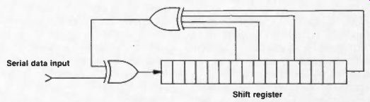
Fig. 2. The basic principle of the signature analyzer.
The oscilloscope as a microprocessor analysis tool still has validity. It can display the shape, frequency, level, and polarity of applied signals. It can present multiple traces for view, enabling relationships to be graphically observed. It can spot noise, glitches, and marginal conditions like no other instrument can, and readily handles an infinite variety of analog signals.
But there are some shortcomings inherent in the oscilloscope which limit its usefulness in testing and debugging microprocessor systems.
Even with delayed sweep, meaningful analysis of long, complex bit streams is an exercise in eyestrain and patience. Its inability to capture random intermittent events or to display fast pulses with low repetition rates makes it only marginally useful in a large percentage of field service applications. Two channels -or four- aren't enough to unambiguously observe the status of eight or sixteen bit wide data paths. Worse, events can only be observed on a scope AFTER a trigger point- and that trigger can only be "one bit" wide, not a preset combination of addresses or data bits.
These limitations don't by any means spell the obsolescence of oscilloscopes-they are still unsurpassed in the observation of noise, analog signals, and other phenomena. And, despite the negative comments, it IS possible to track down a problem in a microprocessor system with a scope. But some more appropriate instruments are clearly needed and, along with some of the less tangible "tools" like board swapping, we should look at a few of them.
Tools--old and new
If you have ever had the pleasure of poking about on a board full of IC's, you are probably familiar not only with oscilloscopes but also digital multimeters, logic probes, "DIP clips," and related implements. As we look now at some of the newer tools, you'll note some fundamental differences.
First, they're relatively "smart"-performing a more complex function than simple display of conditions at the probe tips. Second, the information is extensively processed to provide the user with relatively high-level feedback, such as "truth tables" or timing diagrams. Third, they're expensive, and less likely to appear on the surplus market or on hobbyists' benches.
Let's start with the granddaddy of them all.
Logic analyzers
In 1973, Hewlett-Packard started something of a revolution in circuit design and debugging equipment with their introduction of the Model 1601 logic analyzer. In essence, the analyzer is a recorder of a number of simultaneous data channels, triggered by the occurrence of a preset combination of conditions to produce a stored image of events both before and after the trigger event.
A logic analyzer functions as an expanded oscilloscope, but overcomes many of the scope's intrinsic limitations. It can monitor a large number of channels of data flow or logic states (up to 48 at this writing), such as a 16-bit address bus, 16-bit data bus, and 16 status bits, without the need for constant operator intervention. It can-and this is most useful -operate in a "pre-trigger" mode wherein the events leading up to a crash can be studied after the fact. If a failure, for example, can be associated with the processor's excursion out of a limited range of memory addresses, the analyzer can be set to freeze the captured information constantly circulating through memory at the moment the address bus carries a value greater than the limit. The person studying the problem can then look back with leisure and observe the exact manner in which the failure occurred. With an oscilloscope (even a storage scope), this is impossible.
Modern logic analyzers offer considerable operating convenience as well, normally presenting data on a screen in the user's choice of timing diagrams, binary bit maps, octal or hex data, and sometimes even assembler mnemonics. They also allow glitch detection down to a few nanoseconds.
With all these advantages, logic analyzers generally outperform oscilloscopes on the microprocessor service bench--but they still have a few shortcomings. Like a scope, an analyzer is a passive device, recording and displaying data but unable to manipulate the unit under test. For it to be of any use, some central portion of the ailing system must be functioning or the device is useless and one must revert to conventional techniques.
Comparison testers
Next to logic analyzers, comparison testers occupy a very minor portion of the microprocessor test equipment market. Yet they can, in certain applications, provide extremely useful information. Occasionally, as in the case of the $8950 Model DTO-1 from Gould's Biomation Division, the comparison testing function is incorporated with a logic analyzer in one instrument.
This particular unit contains a tape drive which accepts 3M-type mini cartridges. Each can be used to store up to 100 data traces, which are then accessed by the instrument and compared with the data from the unit under test as a prearranged sequence of steps is followed. The operation allows efficient GO/NO-GO testing of a piece of equipment in the field, once the correct reference traces have been stored by the manufacturer.
Signature analyzers
Hewlett-Packard, again, is responsible for the first of this extremely useful class of instruments.
Their essence is depicted in Figure 2.
Signature analyzers use, typically, a 16-bit shift register like that shown in the figure to "compress" a binary stream of data for comparison with a known-good stream -normally established at the factory. The technique requires that the unit under test provide not only the binary data, but also the clock, a start pulse, and a stop pulse (implying that a piece of equipment must be designed for signature analysis from the beginning). Between the start and stop pulses, the binary data is clocked into the shift register, and at the completion of the interval, the value remaining in the register is displayed on the face of the instrument.
Comparison of this 4-digit hexadecimal number with the one printed in the equipment manual for the tested node (or etched onto the PC board near the appropriate test point) then gives an unambiguous indication of the function of that part of the circuit. Concerning accuracy: the 20 MHz, $990 Hewlett-Packard Model 5004A is said to have a 100% probability of verifying that a correct signal is indeed correct, and a 99.998% probability of catching a faulty one.
There is a fundamental operational difference between logic and signature analyzers. The former presents the operator with substantial amounts of complex information which can be used to determine the operation of a circuit. The user must understand the system intimately and be able to correlate the large quantities of displayed data in order to deduce the nature of a problem. A signature analyzer, on the other hand, while providing a very limited system view which would be useless in the context of the logic analyzer, requires no interpretation: the data represented is either correct or it isn't. By tracing back through the circuit, comparing indicated signatures with those established as correct by the manufacturer, the debugger can generally arrive (with a minimum of system knowledge) at the source of a problem.
Alas, signature analyzers have their problems as well. The unit under test must be self-stimulating because, like the logic analyzer, these instruments are passive and display only as much information as can be extracted from the circuit. The requirement for self stimulation is actually a bit more stringent, as the device must not only be generating some data, but it must also provide the start, stop, and clock signals. This calls for correct functioning of a significant portion of the system even before debugging can begin.
Further, the design which incorporates signature analysis must provide for initialization to a known state prior to testing, or else misleading failure indications could result. Also, there must be some provision for opening feedback loops to accommodate the test, since recursive logic cannot be traced dependably to the source of a problem. These requirements, as well as the need for anticipation during the design of all potentially required test signals, make signature analysis a non-trivial technique to successfully implement.
In-circuit emulators
Ah, but all is not lost. A technique called In-Circuit Emulation, pioneered by Intel, can be married to signature analysis or used alone to solve most of the problems outlined above.
An emulator eliminates the need for the unit under test to be self stimulating; it can be "dead in the water" and still be approached with organized analytical techniques. The trick is the replacement of the system's CPU chip with a cable connected to the instrument, whereupon processor operation can be simulated with either the original application program or, more appropriately, a set of diagnostic routines. Suddenly, much is possible: program execution (and thus system behavior) can be observed one step at a time, complete access to memory and internal registers is possible, and breakpoints--defined places in the flow of a program where the system temporarily halts for close examination-are easily implemented.
With this equipment, any problem can be nailed down in the field.
I mentioned the marriage of signature analysis and emulation--this is an attempt to get the best of both worlds that seems to be gaining favor in the microprocessor test equipment marketplace. With the elimination of the requirement that the unit under test be at least centrally functional, it is possible for the GO/NO-GO simplicity of signature analysis to be available at all times -on a system driven entirely by predefined diagnostics running in an emulator.
One such hybrid unit is the Millennium Systems Microsystem Analyzer, costing about $2390 and requiring an $895 "personality card" for the type of processor under test.
Board swapping
Any discussion of microprocessor system service tools must consider those tools which are not purchased instruments, but rather test techniques. The most prevalent of these is probably the time-honored process of swapping suspect boards with "known-good" ones in order to isolate a failure. It's simple, convenient, and requires no expensive instruments. For these reasons, it is often the technique of choice when customer uptime requirements call for maximum speed in getting a sick system back "on line." In essence, the process is as follows: Verify that a problem exists. If a circuit board is suspect, swap it with a good one and test the system. If it works, you're off the hook; otherwise, swap all the boards and test the system again. If it works, the problem is in one of the original boards; otherwise, it must be somewhere else in the box (power supply, backplane, etc.). If it IS one of the boards, swap them back one by one until the faulty one causes failure: then put the good one in, replace the rest of the original boards, and test again. If a problem remains at this point, the appropriate parts of the procedure should be repeated.
Here, however, is an all-too common occurrence: you reinsert all the original boards and the problem is gone. Hmm. You may have unknowingly cleaned a dirty contact, dislodged a foreign piece of metal, changed the unit's temperature, or caused a re-initialization by cycling the machine's power. Good luck.
There are some other problems with the board swapping approach, beyond the uncertainty implied in the case we just described. A set of spare boards is frequently very expensive, and there is the possibility that a problem which has lain dormant in one of them will be introduced into the system.
That's embarrassing. Also, despite careful attempts to prevent it, it seems that one always accumulates a collection of unknown, intermittent, or suspect boards which, of course, can't be installed in a functioning system without considerable uncertainty.
Diagnostics
It is generally in the interest of system manufacturers to take steps to keep the number of field spares to a minimum. Numerous problems are associated with a large spares inventory, not the least of which are the actual equipment costs and the probability of un-updated units existing after engineering changes take place.
(Talk about servicing nightmares- installation of a known-good spare causes new problems because the revision levels are different!) One of the approaches used to improve the efficiency of field testing at this level is the inclusion of built-in diagnostic programs. If these are well designed, it is often possible to zero in on a fault without even opening the box.
Without considering in depth the vast range of self-testing philosophies which exist, we note that they can be implemented at one of three levels: permanent installation in the system with access via a switch or a special command, temporary installation in the system at service time (accomplished by plugging in a "Diagnostics" board) or execution on an in-circuit emulator like that discussed earlier. Any of these approaches call for careful planning and documentation so that the results will not be misleading.
Testability
Now that we've discussed the major classes of microprocessor service tools, we can close with a mention of the fact that much of their usefulness depends upon designed-in testability.
The availability of techniques such as combined emulation and signature analysis allows close communication between the field service force and the engineers behind the design. This makes everyone happier, especially the customers.
But if a system is created with blatant disregard for the possibility of its eventual failure, then even the most sophisticated of the available tools is insufficient. This lesson is being learned across the entire industry, and as time goes on and complexity grows greater, more and more attention will be paid to the requirements of equipment service.
It's a pleasant and long-overdue change.
(source: Electronic Technician/Dealer)
Also see: Link |