Indoor antennas generally represent at best a poorcom promise of performance vs. complexity. Circular polarization and some new designs have recently begun to make life easier, however.
By Stan Prentiss
CP--as circular polarization is familiarly known -presently does more for indoor rabbit ear antennas (Fig. 1) than any thing else, because CP consumer out door arrays are not yet generally avail able, although several types are now undergoing tests in Illinois and New York. This is mainly because rabbit ears are primarily vertically and not horizon tally polarized as are the standard out door receiving antennas.
Theoretically, antennas may be both radiators (transmitters) and receptors (receivers), and this is very true for relatively low-powered 2-way mobile radio and base stations. But the power difference between 4 and 100 watts, versus a 10- or 50-thousand watt broadcast station (Fig. 2) is such that you wouldn't want either the expense or the mammoth structure of such a radiator at or near your house. Therefore, relatively tiny receptors which can translate radiated electromagnetic energy into microvolts in the U/V spectrum between 54 and 890MHz, some or many miles distant from the various transmitters, are both satisfactory and sufficient.
Naturally, if your receptor is not cut to precise frequency and has only a pair of driven elements without directors or reflectors, any and all signals surrounding your resultant Vee-shaped ears are precious. So when a broadcast station reinforces its horizontal signal with an other of equal power and intensity vertically, the "ears" are considerably more receptive. And this is especially true for uhf signals since they are of higher frequencies and will readily pass through smaller window and other entrance areas in residences and apartment buildings. CP, therefore, is of more than passing fancy in the more densely settled areas immediately. Later, after suit able outside arrays are designed and in the hands of consumers, many more broadcast stations will also adopt CP, and you can then expect at least a 3dB increase in received signal strength along with considerable ghost (often called secondary image) cancellation.
Seventeen stations already have CP and 14 more are installing. According to broadcast product manufacturers Harris and RCA, the following television stations are already equipped with CP: WESH-TV, Daytona Beach, Fla.; WCIX TV, Miami, Fla.; WWL-TV, New Orleans, La.; KBYU-TV, Provo, Utah; WAST, Albany, N.Y.; WNET, New York, N.Y.; WOR-TV, New York, N.Y.; WLS-TV, Chicago, ILL.; XTEV, Tijuana, Mexico; WTTV, Indianapolis, Ind.; WRAL-TV, Raleigh, N.C.; WTVD, Durham, N.C.; WFMY-TV, Greensboro, N.C.; WITN TV, Washington, N.C.; WPBT, Miami, Fla.; KCPQ-TV, Tacoma, Wash.; KSTVV, Tacoma, Wash.
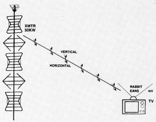
Fig. 1. A VHF circularly polarized signal showing both vertical and horizontal
components reaching a standard pair of rabbit ears.
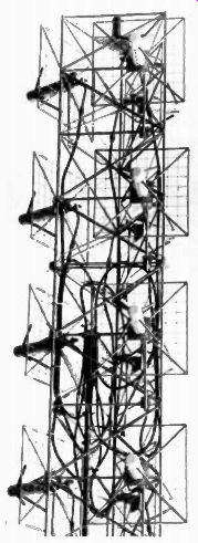
Fig. 2. RCA's TBJ type CP antenna for channels 7-13. (Courtesy RCA)
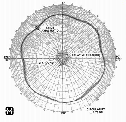
Fig. 3. A typical quality horizontal pattern from a HARRIS VHF broadcast antenna
(Courtesy HARRIS Corp) --- MEASURED HORIZONTAL RADIATION PATTERN MECHANICALLY
ROTATING DIPOLE ILLUMINATION
Others in the process of converting or under construction are: Radio Difusor, Sao Paulo, Brazil; TV National, Santiago, Chile; TV Litoral, S.A., Argentina; WECT-TV, Wilmington, N.C.; WCTI-TV, New Bern, N.C.; WVTM, Birmingham, Ala.; WB'TVV, Florence, S.C.; WXIA-TV, Atlanta, Ga.; WLNE, New Bedford, Mass.; WABC-TV, New York, N.Y.; WBNS-TV, Columbus, Ohio; WNCT-TV, Greenville, N.C.; KCRA-TV, Sacramento, Calif.; Radio Caracas, Venezuela.
Area coverage (Fig. 3) in some in stances following CP installations is so good that figures showing these increases are difficult to come by. But what this means to the consumer is that he or she will have better signals, less ghosting, and new broadcast equipment (Fig. 4) which should deliver maximum 4MHz bandpass signals to the host of new receivers that now have 4MHz luminance passband comb filters and can produce a full 330 lines of horizontal resolution.
What is CP? For those who are not yet familiar with circular polarization, here is a brief description of what it does and a look at its broadcast transmission means.
First used in broadcasting during the 1960s to help FM rise from a severe economic slump, right hand circular polarization was finally approved by the Federal Communications Commission in 1978 for TV applications after extensive testing by WLS-TV in Chicago and KLOC-TV in California.
If a part of orthogonal dipoles (Fig. 5) are placed in near proximity and excited by signals 90 degrees out of phase, a constant magnitude field is created that rotates either right or left, depending on the phase of the two signals. Any antenna receiving these signals is subject to a constant signal level, regardless of its horizontal or vertical orientation (direction). These two fields, however, maintain their separate vertical and horizontal polarities, but travel along the same axis and in the same direction.
Since both are equally strong and in dependent, separate and equal transmitters are required to generate their outputs.
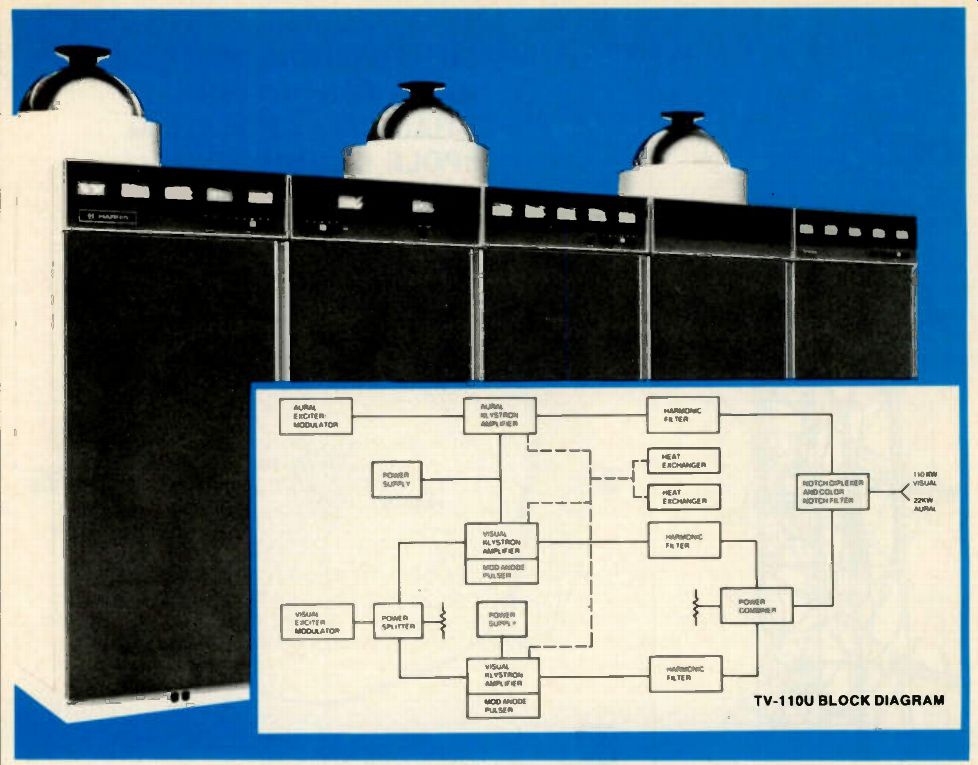
Fig. 4. HARRIS' 110 KW, TV-110V, UHF color TV transmitter, designed for unattended
operation. (Courtesy HARRIS Corp.). TV-110U BLOCK DIAGRAM
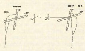
Fig. 5. CP between transmitter and receiver. Note right hand polarized antenna
connections.
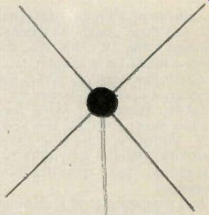
Fig. 6. A newly patented CP indoor antenna has 2.15 dB gain plus 13 dB ghost
rejection.
In approving CP, the FCC opted for right hand polarization, and so all CP TV receiving antennas must also be similarly polarized. This means that any left hand "bounce" or secondary image, out of phase with the main signal, will usually either be substantially or totally rejected, considerably reducing ghosting effects. This does not mean that the present horizontally polarized antennas will be affected since one component of the CP signal is still travelling in the usual, standard horizontal plane. But it does mean that any and all vertically polarized whips (vertical dipoles), and the ordinary rabbit ears will benefit accordingly since they depend more on the signal's vertical component than on the horizontal. CP, then, will be good for both VHF and UHF where there is ghosting, co-channel or adjacent channel interference, poorly oriented antennas, multipath interference, intermittent field strength coverage, and the usual problems associated with whips and rabbit ears.
Is it any wonder that North Carolina, New York, and Takoma. Washington are making haste to have highly useful CP transmissions on the air before much of the remainder of the U.S.? Other cities and communities, obviously, will certainly come around in time.
CP receiving antennas CP consumer antennas have already been designed for experimental use by JFD, Channel Master, and Blonder Tongue, but have not in the past been offered to the general public. We do know, however, that crossed Yagi and log periodic types are now being engineered, and an indoor (Fig. 6) CP 4 element crossed dipole array has been patented by Harris' Jeff Steinkamp, Quincy, Ill., and is being tested by nine different CP broadcasters at this writing.
Production was scheduled for early 1981, with the promise of a reasonable retail price not yet announced. Mr. Steinkamp claims gain over standard rabbit ears of 3dB, ghost reduction of 78%. and 300-ohm input connections.
The only catch is that separate antennas will be required for channels 2-6 and FM, 7 through 13, and 14 through 83. We have also just learned that 150 Channel Master 3-element Yagi CP antennas cut for channels 7 through 13 have been shipped to KSTW, Tacoma, Washington, for CP reception there. So the race is really on, both indoors and out.
For now, however, be patient, for just like the first hi-low, folded separate vhf receptors for black and white, CP manufacturers will have to matriculate through the various learning curves until a combined u v circularly polarized antenna can be structured to serve all 82 FCC assigned channels. That could take a while, naturally, but in the mean time, all those with CP stations in their areas would do well to climb on the video bandwagon immediately for considerably better pictures. You'll be glad you did!
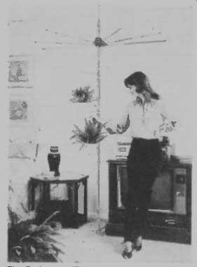
Fig. 7. An amplified indoor antenna that works.
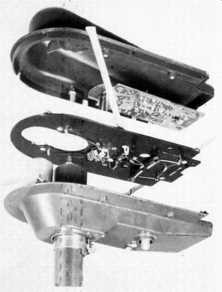
Fig. 8. The inside of Winegard's AT Thousand amplified antenna series for
both indoor and outdoor use.
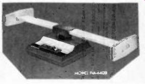
Fig. 9. Another amplified indoor antenna from Winegard. It works quite well
on FM Whips and Rabbit Ears
All sorts of radiator/receptors have been designed for outdoor use in TV antenna applications, as well as indoor, but few originals have actually survived over the years except corner reflectors, bow ties, Yagis, and the familiar indoor circular elements-most of which are for uhf applications and not vhf.
With wavelengths much longer and antenna dimensions considerably larger for vhf, any similarity between indoor and outdoor 54 to 216MHz signal transducers has really not been possible except among some ill-fated window ledge units that were both narrowband and rigged for black and white reception; hence, the ubiquitous rabbit ears, which are nothing more than a pair of telescoping metal rods some 40 inches long, and fastened to a hank of twin lead that connects to vhf terminals on the TV set.
It's not an especially scientific way to go since simple dipoles for channel 2, as example, should be cut for 102 inches, and those for channel 13, 27 inches- all without reflectors, directors, tuned elements, coupling harnesses, or any thing else that affects the precise receptor characteristics of the antenna.
Then top this off with a generalized Vee rather than a pure horizontal receiving dipole, and you have the usually enormous problems surrounding any type of indoor antenna.
Even the newer multi-element indoor rigs with various capacitance switches, used for minor tuning and to minimize extraneous signals, only aid a little rather than a lot. You just can't pull in a signal without adequate receiving equipment, even with gimmicks. One must also remember that an inert metal antenna has absolutely no real "gain" (increase in received signal strength) unless actually amplified; and that, of course, is the subject of our next topic.
Amplified indoor antennas
At one time or another various manufacturers have tried to install amplifiers among the indoor offerings, but without notable success. There have been round ones, rectangular ones, Yagis, plain rabbit ears and many more. But the only antennas we've seen recently that work satisfactorily-either in or out of doors- are directional arrays with sufficient active elements and amplifying electronics to attract enough electromagnetic energy to put an adequate picture on television screens. Otherwise, few, if any, of the other designs really work. And for this you have to have signals between a minimum of 100 microvolts (best tuners) to 1,000 microvolts for overall good set performance of every variety.
The Winegard Co., of Burlington, Iowa, fortunately has recently introduced such an antenna (fig. 7) for TV that we have had under continuous test for 6 months. Three additional uhf stations are now received where no signal existed previously, and vhf stations as far away as 30 plus miles are usable, although not perfect. All this takes place in a walkup steel and brick apartment building on the second floor.
The assembly looks like a 4-way clamshell (Fig. 8) with baluns and the necessary transistorized electronics mounted on two printed circuit boards in between. Noise figure for vhf is only 3dB and for uhf 6dB, while gain amounts to 16dB for vhf and 8dB for uhf. Front to-back ratios are 16 and 10dB, respectively. There is also diode protection for the transistors and, of course, a 12-volt transformer isolated power supply for rotor and set. Turning radius amounts to 30 inches. Winegard says this is the same preamplifier (with FM rejection circuitry) that's been used in the Gold Star line for the past five years.
Actually, the unit is available for both attic and outside installations, but you're really better off with a standard, first line chimney mount receptor under outside conditions than with this specialized equipment. Models are AT-5000 ant. and mast, AT-4000 with rotator and signal amplifier. AT-3000 with amplifier.
AT-2000 with rotator only, and AT-1000 for basic antenna without either rotor or amplifier. Suggested retail prices range from $36.75 to $127.75.
For FM and stereo, Winegard is also offering a pair of 19-inch amplified FM 4400 and FM-2400 table top walnut and gold tone antennas with good to excel lent performance (Fig. 9.). They're at tractive, and the amplified version may be plugged into the switched outlet of your stereo so it will be turned off when ever the set is. In out tests. the FM-4400 outperformed TV input (for f-m) corning down from an outside antenna on 75 ohm coax. Suggested retail . $39.95 and $71.95.
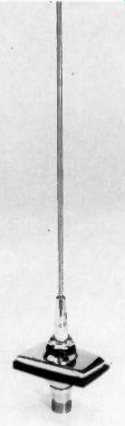
Fig. 10. A concealed CB AM FM antenna.
This is the Ford version.
CB is still here, too
And for the little ladies and boys, young or old, who still have the highway spirit of adventure lingering, why not a concealed AM-FM-CB antenna? Useful in all sorts of emergencies such as flat tires and accidents, get-acquainted sessions, or smokey talk, a vertical steel whip of modest proportions can only help, not hinder. Antenna Specialists, of Cleveland, Ohio, has a very special series of MS or M cowl mount disguised antennas of 17-7 PH tapered stainless steel built especially for Ford, Chrysler, GM, etc., that can do wonders (Fig. 10). Forty eight inches high, with an electronic tri-band coupler, this series features a voltage standing wave ratio (VSWR) of better than 2:1 on all channels, good road range, and a tunable core for maximum a-m, sideband output and minimum loss. Installation is simple and cables fit nicely through existing body holes-at least on Ford and Mercury Cougar, anyway. You'll enjoy good AM-FM radio, too, as the truckers' call of "a super trooper northbound at the 42-mile marker" comes crackling down the superslab.
(source: Electronic Technician/Dealer)
Also see: