One if by land, and two if by sea..." says the famous poem by Longfellow commemorating the midnight ride of Paul Revere in April of 1775. Revere's fellow patriot, who hung the two (if by sea) lanterns in the steeple of the Old North Church of Boston 200 years ago, was engaged in communicating by modulation, just as surely as today's CBer who presses the PTT switch on his microphone. For modulation simply means variation, or change-and it's modulation, whether you're changing the number of lanterns hanging in a church steeple, or using electronic circuitry to change the radio wave emitted by an antenna in accordance with your voice.
All communication is by modulation. For centuries, the American Indians sent messages by "modulating" a smoke stream with a wet blanket, and primitive tribes have long communicated by modulating the beat of their jungle drums.
Later, semaphore flags were used to send messages by modulating their position. Even these words you are reading can be considered modulation of the surface of a piece of paper with spots of ink.
But almost all of today's long-distance instantaneous communication is carried out by modulating radio waves.
In fact, this means of communicating is now so commonplace that even the Man the Street unknowingly refers to modulation when he speaks of "AM" and "FM". These familiar abbreviations stand for Amplitude Modulation and Frequency Modulation, respectively, and refer to the two common methods of changing a radio wave to make it broadcast words or music from one place to another.
Introducing the Carrier. A radio wave broadcast from the antenna of a transmitter is, in the absence modulation by speech or music, an unchanging, constant sine wave, as shown in Fig. 1.
It is as constant and as unchanging as the steeple of the Old North Church, and conveys no more information than a steeple. It simply gives you something to monitor for the possible later appearance of a signal.
Just as the steeple was a support or carrier on which to hang the information-giving lanterns, so the radio wave becomes the carrier upon which the speech or music is "hung". In fact, the unmodulated wave is usually referred to as the carrier.
The carrier may be shown as a simple sine wave, as in Fig. 1.
The height, or amplitude of the wave, indicates the strength of the signal, while the time it takes the wave to complete a certain number of cycles determines the spot on the radio dial where the signal will be received. For example, as shown in Fig. 2a if it takes only a millionth of a second for the carrier to complete seven cycles, then it will complete 7,000,000 cycles in one second, and the signal will appear on a receiver's dial at the 7,000,000-cycle-per-second (7-megahertz) point, which is on the edge of the 40-meter ham band. Such a carrier has a frequency of seven MHz.
On the other hand, a carrier taking longer to complete the same number of cycles-say, seven cycles in 10 millionths of a second (Fig. 2b) would complete only 700,000 cycles in one second, and would be found on the dial at 700 kHz (700 thousand Hertz), which is in the standard broadcast band.
As can be seen from the above numbers, carrier frequencies are normally very high-much higher than the speech or music (audio) frequencies which we will cause the carrier to carry. For example, when a flutist plays the note F above middle C, he produces vibrations in the air which can be visualized as in Fig. 2c. Here, the time for 7 vibrations is only one fiftieth of a second, which is a frequency of only 350 cycles per second (350 Hertz).
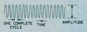
Fig. 1-Unmodulated carrier (RF) wave.
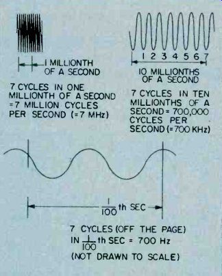
Fig. 2-Three different frequency waves. 700 Hz (bottom) is partial, not
drawn to same scale as the two higher frequencies.
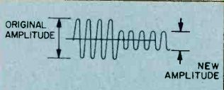
Fig. 3-Simplified amplitude modulation of the RF carrier wave.
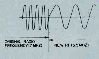
Fig. 4-Simplified frequency modulation of the RF carrier wave.

Fig. 5-If the frequency modulation were a simple change from one RF carrier
frequency to another, an AM receiver could receive it if retuned.
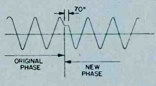
Fig. 6-Simplified phase modulation of the RF carrier wave.
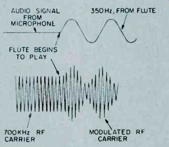
Fig. 7-The audio signal (sound) modulates the RF carrier wave.
But a constant (unchanging) carrier wave conveys no information. Something about the wave must be varied (modulated) to convey information to the listener. What can be changed, so that the listener can recognize that a signal has been sent to him? AM and FM. Looking again at Fig. 1, you can see that a carrier has two obvious characteristics--its height, or amplitude, and its frequency. Changing either of these can cause a receiver to recognize that a message has been sent.
If the amplitude is changed, we call it amplitude modulation, or AM. If the frequency is changed, we call it frequency modulation, or FM. A very simple type of AM is shown in Fig. 3. Here the amplitude of the carrier wave has been changed suddenly to half its former value.
This change in amplitude is a simple form of AM, and can convey simple messages. If Paul Revere had been a CBer, he could just as easily have prearranged a code signal which said ".. . one drop in carrier amplitude if by land; two drops in carrier amplitude if by sea ..." and served the American cause just as well (though Longfellow's poetry might have suffered). The other obvious characteristic of the carrier wave of Fig. 1 is its frequency. We can also modulate this characteristic, as shown in Fig. 4. Here, instead of a sudden change in amplitude, there is a sudden change in frequency, from 7 MHz to 3.5 MHz. This is a very simple form of FM, and can also be used to convey simple messages.
Since the drop in frequency represents a shift in the carrier's location on the dial, as shown in Fig. 5, two receivers, one tuned to 7 MHz and the other to 3.5 MHz, could detect this shift in frequency, and the listener could interpret it as a signal, according to a pre-arranged code.
What's PM? While the Man in the Street has made AM and FM household phrases, these modulation methods are only two of the three ways a radio frequency carrier wave may be modulated. The third method, Phase Modulation, or PM, although virtually unknown to most people, is nonetheless extremely important in such fields as data transmission and color television.
Phase modulation can be visualized as in Fig. 6. Here, neither the amplitude nor the frequency is varied, but the carrier is made to pause for a moment, and then to continue as a sine wave slightly delayed from the original.
This delay is called a phase shift. Phase shift is usually measured in degrees. A phase shift equal to the time needed for an entire cycle is 360°. In the sketch, a sudden phase shift of about 70° (less than a quarter cycle) is indicated. By suitable receiver circuitry (found in every color TV receiver), this sudden change in phase can be interpreted as a signal. In color TV, it might represent a shift in hue from green to yellow.
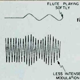
Fig. 8--Smaller audio signal modulates the RF carrier wave less.
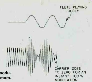
Fig. 9--Louder audio signal (sound) modulates the RF carrier wave to maximum.
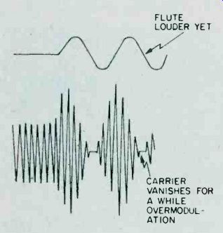
Fig. 10-Further increase in amplitude of audio signal causes overmodulation.
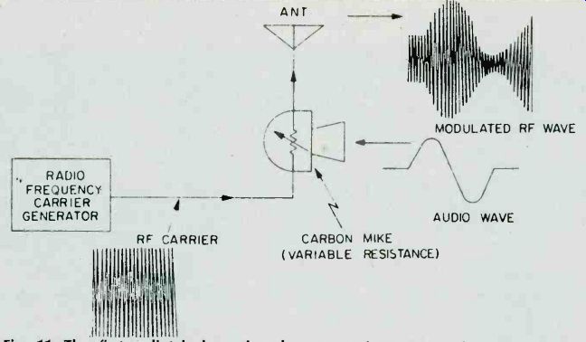
Fig. 11--The first radio telephone broadcast transmitter, invented by Canadian
Reginald Fessenden who broadcast voice and music to a few ships at sea
on Christmas Eve, 1905. It worked, but was very noisy.
Amplitude Modulation--A Closer
Look. The sudden drop in amplitude shown in Fig. 3 is a good way to show the general scheme of AM, but it fails to tell us very much about how AM is used, every day, in our AM receivers and CB rigs. Here there are (hopefully) no sudden shifts in carrier amplitude, but instead, there is a remarkable recreation of speech and music from a distant transmitter. How is this done? To explain, let us assume that our flutist stands before a microphone in a broadcasting studio, ready to play his 350-Hz F-above-middle-C. Let's also assume that the broadcasting station is assigned a carrier frequency of 700 kHz. Figure 7 shows how the carrier wave will appear just before the flutist plays, and just after he begins.
As you can see, the 350-Hz audio tone from the flute causes the amplitude of the carrier to rise or fall in accordance with the rise or fall of the flute wave. Note that both the top and bottom of the carrier wave are affected by the flute waveform. It is as though the carrier had been squeezed into a snug-fitting envelope, forcing it to conform to the waveform of the flute sound. The shape thus formed by the tips of the modulated carrier wave is often called the envelope.
The envelope of an amplitude-modulated carrier is therefore a good replica of the audio waveform coming from the studio microphone. Every shading, every change, in the sound striking the microphone will be faithfully traced out by the tips of the carrier wave. For example, if the flutist were to play more softly, the result will be as in Figure 8.
If he plays more loudly, Figure 9 is the result. You will note that in Fig. 9 the amplitude modulation is so intense that, at one point, the carrier's amplitude goes to zero for an instant. This is called 100% modulation, and represents the loudest sound AM can handle.
If the flutist plays even more loudly, the result is as shown in Fig. 10. As the figure shows, the envelope is no longer a faithful replica of the original audio waveform, so the listener will receive a distorted sound. This condition is called overmodulation, and is undesirable.
Hardware for AM Systems. One of the most-straightforward methods of producing AM is the method invented by the Canadian Reginald Fessenden, in 1905. In his system, a radio frequency generator produced the carrier wave, which was fed to the antenna through a carbon (variable-resistance) microphone. See Fig. 11.
Since a carbon microphone varies its resistance in accordance with the speech or music, the microphone in this primitive system acted as a valve to allow more or less of the RF carrier wave to pass to the antenna. In this way the carrier wave broadcast by the antenna was amplitude modulated by the sound waves striking the microphone.
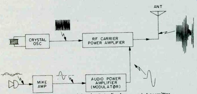
Fig. 12--Typical amplitude-modulated RF (radio frequency) transmitter.
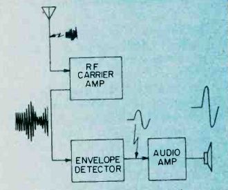
Fig. 13--Block diagram of receiver for amplitude-modulated radio frequency
(RF) signals.
More Up-to-date Modulation
Methods. Although nobody puts carbon microphones in series with antennas any more, the more modern modulation methods, such as those found in AM broadcast transmitters or CB transmitters are still rather similar to the primitive carbon-mike method. The typical modern AM system (Fig. 12), still employs an oscillator (which is crystal-controlled, to ensure that the carrier frequency is constant, and thus is found at a known spot on the dial), and a power amplifier to strengthen the carrier before feeding it to the antenna.
The amount of "strengthening" is controlled by the audio signal, and the music to a distant point.
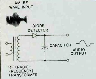
Fig. 14--Simple receiver of amplitude-modulated (AM) RF signals.
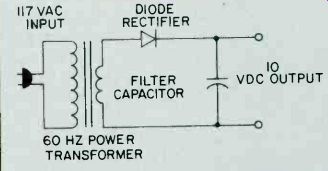
Fig. 15--DC power supply from AC house current has circuit similar to
that of the simple AM receiver.
Receiving the Signal. At that distant point, we all know that the carrier power delivered to the antenna is in this way amplitude-modulated and the radiated carrier will convey the speech or wave may be intercepted by a suitable antenna-and applied to a receiver. A simple receiver is shown in block diagram form in Fig. 13. Here, the weak signal from the antenna is first amplified in a carrier-wave amplifier, (an RF (radio frequency) amplifier, and applied to a detector which can extract the original audio signal from the amplitude-modulated RF carrier. This audio wave is further amplified and then fed to a loudspeaker, which re-creates the original speech or music.
The Detector-Heart of the Receiver. By looking at Fig. 13, you can see the detector is the heart of the AM receiver which extracts the original signal from the amplitude-modulated carrier. The circuit that does this job is surprisingly simple. It resembles very closely the circuit of a typical power supply. In an AC power supply, when 117-volts AC is applied at the input plug, a DC voltage appears at the output. If, because of a brown-out or for some other reason, the 117 volts at the input drops to, say, 105 volts, the DC output will drop correspondingly. In a power supply, this output drop is undesirable-we want the DC output to remain constant even though the input AC varies. Notice that the drop in voltage of the 60-Hz power line input from 117 volts to 105 volts is actually amplitude modulation, of the 60-Hz input sine wave, and the drop in the output DC has "detected" the AM that occurred at the input! This is shown in Fig. 16.
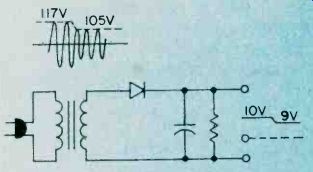
Fig. 16--Changing amplitude of voltage input to power supply provides
changed (modulated) output.
So a simple AM detector may be thought of as a power supply arranged to change its output very quickly in accordance with the amplitude changes in the AC (carrier) at its input. And, since these fluctuations in amplitude of carrier represent the original audio signals, the "power supply" (detector) output will be the same as the original audio.
It's interesting to note the power supply's undesirable trait, unsteadiness in output when the input is unsteady, is the useful operating characteristic of the same circuit when used as a detector!
=======