One of the most thought-provoking discoveries of modern physics is the fact that matter and energy are interchangeable. Centuries of scientific head-scratching about the nature of matter, the mystery of fire, and the once-terrifying crack of lightning have all come to focus on the smallest particle that is the building block of any given substance: the atom. An atom is necessarily matter and yet this atom of matter can undergo nuclear fission and release quantities of energy that are beyond the imagination. In the atom lies the secret of all phenomena.
By the beginning of the 19th century, the atomic theory of matter-which actually originated in 5th century Greece when the atom was named-was firmly established. It was due primarily to the efforts of 17th century scientists who-actually working in the tradition of medieval alchemy-sought the prime constituent of all matter. Mainly through the work of John Dalton, whose investigations as to how various elements combine to form chemical compounds, it came to be regarded that an atom was the indivisible and indestructible unit of matter.
This viable and working view of the indestructible atom served science until 1897 when the atom itself was found to be destructible! To anyone concerned with electricity or electronics, the year 1897 is a memorable one: it was the year J. J. Thomson, the English physicist, identified and experimentally revealed the existence of the first subatomic particle--the electron! The First "Electronic" Experiment. We blithely speak of electricity as the flow of electrons yet, often, we are little aware of the great body of research that went into elucidating this fundamental of basic electricity. In fact, before the discovery of the electron, convention held that the flow of electric current was in the direction that a positive charge moved. This convention of positive current, being the flow of positive charges and opposite to the direction of electron flow, is still found to be useful in circuit analysis and is used even today.
Thomson's experiment established that a particle much lighter than the lightest atom did indeed exist. The electron, as it was named, was the first subatomic particle to be defined.
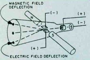
Fig. 1. Electron beam, like that in a TV picture tube (CRT), can be deflected
magnetically or by an electric field. Force needed "measured" the
electron.
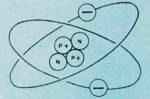
Fig. 2 . Charge of each electron balances that of a proton. Other particles affect atomic mass but can be omitted in study of electronics.
The experiment was conducted utilizing a rudimentary version of a cathode ray tube-the modern version of which is in almost every home today in the form of the television picture tube. Before Thomson's experiment, it was discovered that when electric current was passed through a gas in a discharged tube, a beam of unknown nature traveled through the tube from the negative to positive terminal (Opposite to the direction conventionally held as the direction of the flow of current). This "cathode ray" beam also traveled in a straight line and was deflected by electric or magnetic forces applies perpendicular to the beam. What Thompson did was to use these facts to determine for one of the mysterious particles comprising the beam of cathode rays the relationship of its mass, m, to its electric charge, e. By deflecting the beam With a known electric force (Fig. 1) and then measuring what magnetic force applied in the opposite direction would bring the beam back to its original undeflected position, Thompson could determine the relationship of e to m. He established a definite value for e/m and thereby "discovered" the electron which as we now know, is 1,837 times smaller, in mass than the lightest atom, the hydrogen atom. It also carries the smallest charge that occurs in nature; every electric charge is actually an integral multiple of the charge of the electron.
From Minus to Plus. With the discovery of the electron, it was still over a dozen years into the 20th century before a graphic conception of the atom evolved. Since the atom is electrically neutral and electrons are negatively charged, the existence of positively charged particles was a necessity, and the existence of a proton was postulated. Eventually the nuclear model of the atom was evolved. Each atom was conceived to resemble a solar system in miniature. The nucleus-positively charged-is surrounded by a number of electrons revolving around it; the charges balance and the atom is electrically neutral (Fig. 2). Further research in the 20th century has gone onto reveal more elementary particles than you can shake a stick at: neutrons, positrons, neutrinos, mesons, quarks, and more. The number continues to grow and yet the ultimate nature of matter remains a riddle. But, in a discussion of basic electricity, only the electron and proton need concern us.
Electrons in Orbit. An atom of matter has a number of electrons orbiting around its nucleus. A hydrogen atom for example, has a single electron; carbon on the other hand has six. These electrons are arranged in rings or shells around the central nucleus--each ring having a definite maximum capacity of electrons which it can retain. For example, in the copper atom shown in Fig. 3 the maximum number of electrons that can exist in the first ring (the ring nearest the nucleus) is two. The next ring can have a maximum of eight, the third ring a maximum of 18, and the fourth ring a maximum of 32. However, the outer ring or shell of electrons for arty atom cannot exceed eight electrons. However, heavier atoms may have more than four rings.
The Outer Orbit. The ring of electrons furthest from the atom's nucleus is known as the valence ring and the electrons orbiting in this rings are known as valence electrons. These valence electrons, being further from the nucleus, are not held as tightly in their orbits as electrons in the inner rings and can therefore be fairly easily dislodged by an external force such as heat, light, friction, and electrical potential. The fewer electrons in the valence ring of an atom, the less these electrons are bound to the central nucleus. As an example, the copper atom has only one electron in its valence ring.
Consequently, it can be easily removed by the application of only the slightest amount of external energy. Ordinary room temperature is sufficient to dislodge large numbers of electrons from copper atoms; these electrons circulate about as free electrons. It is because of these large numbers of free electrons that copper is such a good electrical conductor. There could be no electrical or electronics industry as we know it today if it were not for the fact that electrons can fairly easily escape, or be stripped from the valence ring of certain elements we refer to as "conductors."
Electronic Charges. If an electron is stripped from an atom, the atom will assume a positive charge because the number of positively charged protons in its nucleus now exceeds the number of negatively charged orbiting electrons. If, on the other hand, the atom should gain an electron, it will become negatively charged as the number of electrons now exceeds the protons in its nucleus. The atom with the deficiency of electrons is known as a positive ion, while an atom with a surplus of electrons is known as a negative ion.
Presence of an electrical charge on a body can be illustrated by use of an electroscope (Fig. 4). Two leaves of aluminum or gold foil hang from a metal rod inside a glass case so they're free from air disturbances. When the metal rod is touched by a charged body, the leaves acquire static electricity of the same polarity and, since like charges repel, they stand apart. The greater the charge, the further apart the leaves spread.
Electron Flow. When an electrical conductor is placed between these two oppositely charged bodies, free electrons are attracted by the positive body-free electrons will move through the wire. This movement of free electrons will continue only until the excess of electrons is equally divided between the two bodies.
Under these conditions, the charges on both bodies will be equal and the electron flow will end.
In Fig. 5 are a battery, lamp, and connecting leads , between the battery and lamp. In this instance, the battery serves as an electric charge pump-free electrons continually developed at its negative terminal by chemical action flow through the connecting leads and lamp back to the positive terminal of the battery by the attraction of oppositely charged bodies. The battery, connecting leads, and lamp form an electrical circuit which must be complete before the free electrons can flow from the battery's negative terminal to its positive terminal via the lamp. Thus, the battery serves as a source of potential difference or voltage by continually supplying a surplus of electrons at its negative terminal.
Summing up, we can say a flow of electric current consists of the movement of electrons between two oppositely charged bodies.
We cannot progress very far into the study of electricity without first becoming familiar with the basic properties of electrical circuits. Just as we define distance in feet and inches, so do we define electrical properties in specific terms and units.
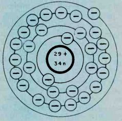
Fig. 3. The number of electrons to each ring are limited--2 in first;
8 in second; 18 for the third; and a total of 32 in fourth orbital ring.
The last ring of electrons cannot have more than eight electrons.
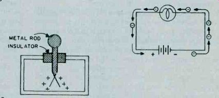
Fig. 4. Electroscope is a simple device to indicate electrical charges
that are too weak to be measured with standard meters. The two leaves of
gold foil pushed apart in the presents of a charged surface.
Potential. Earlier, we saw that an electric charge-difference has to exist between the ends of an electrical conductor in order to cause a flow of free electrons through the conductor. This flow of electrons constitutes the electric current. The electric charge difference, or potential difference, exerts a forces on the flow of free electrons, forcing them through the conductor. This electric force of pressure is referred to as electromotive force, abbreviated EMF.
The greater the charge or potential difference, the greater will be the movement of free electrons (current) through the conductor as there will be more "push and pull" on the free electrons. The symbol used to designate electrical potential is the letter E which stands for electromotive force. The quantity of EMF is measured by a unit called the volt. Hence, the common name most often used in place of EMF is voltage.
Current Intensity. We have learned that an electric current consists of a flow of charge carriers (generally free electrons) between two points of different electrical potential. The rate of flow of these charges determines the intensity or strength of this current flow. Current strength is expressed in units known as amperes. One ampere of current flows in a circuit when 6,240,000,000,000,000,000 electrons flow out of a negative terminal, through a conductor, and back into a positive terminal in one second. The symbol for the ampere is the letter I which stands for intensity.
Resistance. The flow of electric current through a conductor is caused by the movement of free electrons present in the atoms of the conductor. A bit of thought then indicates that the `greater the number of free electrons present in the atoms of a particular conductor, the greater will be its electrical conductivity. Gold, silver, and copper rank as excellent electrical conductors, as their atoms readily release free electrons.
On the other hand, the atoms of such elements as sulphur have almost no free electrons available and they are thus very poor electrical conductors. Such materials are known as electrical insulators. Between these extremes lie elements such as carbon whose atoms have a moderate number of free electrons available and thus are moderately good electrical conductors.
Even the best electrical conductors offer some opposition to the passage of free electrons. This opposition is called. resistance. You might consider electrical resistance similar to mechanical friction. As in the case of mechanical friction, electrical resistance generates heat. When current flows through a given resistance, heat is generated; the greater the current flow, the greater the heat. Also, for a given current flow, the greater the resistance, the greater the heat produced.
Electrical resistance can be both beneficial and undesirable. Toasters, electric irons, etc. all make use of the heat generated by current flowing through wire coils.
Resistance is also often intentionally added to an electrical circuit to limit the flow of current. This type of resistance is generally lumped together in a single unit known as a resistor.
There are also instances where resistance is undesirable. Excessive resistance in the connecting leads of an electrical circuit can cause both heating and electrical loss. The heating, if sufficient, can cause a fire hazard, particularly in house wiring, and the circuit losses are a waste of electrical power.
Electrical resistance is expressed by a unit known as the ohm, indicated by the letter R. An electrical conductor has a resistance of one ohm when an applied EMF of one volt causes a current of one ampere to flow through it.
Resistance Factors. There are other factors beside the composition of the material that determine its resistance.
For example, temperature has an effect on the resistance of a conductor. As the temperature of copper increases, for example, its resistance increases. The increase in temperature causes the electrons in the outer ring of the atom to resist release to the free electron state. This increase in resistance is known as a positive temperature coefficient. Not all conductors show this increase in resistance with an increase in temperature; their resistance decreases with an increase in temperature.
Such materials are said to have .a negative temperature coefficient. Certain metallic alloys have been developed which exhibit a zero temperature coefficient: their resistance does not change with changes in temperature.
As you might suspect, the length of a conductor has an effect upon its resistance. Doubling the length of a conductor will double its resistance. By the same token, halving the length of a conductor will cut its resistance in half. Just remember that the resistance of a conductor is directly proportional to its length.
The cross-sectional area of a conductor also determines its resistance. As you double the cross-section of a conductor, you halve its resistance; halving its cross-section doubles its resistance. Here again, the "why" of this is pretty easy to see: there are more current carrying electrons available in a large cross-section conductor than in a small cross-section conductor of the 'same length. Therefore, the resistance of a conductor is inversely proportional to its cross-sectional area.
Circuit Relationship. Now that we have a basic understanding of voltage, current, and resistance, let's take a look at just how they interact under circuit conditions.

Fig. 5. Electron flow in any circuit is from negative to positive.
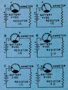
Fig. 6. In A, B, and C, the value of the resistor remains constant while
the supply voltage is altered with a resulting current change.

Fig. 7. Battery voltage A, B, and C is held constant while resistor is
halved and doubled in value. Resulting current changes are basis for Ohm's
law.
Fig. 6A shows a battery, ammeter (a device to indicate current strength), and resistor connected in series. Notice that the ammeter indicates that 4 amperes are flowing in the circuit.
Fib. 6B shows the identical setup with the exception that the battery voltage has now been doubled. The ammeter now shows that twice the original current, or 8 amperes, is now flowing in the circuit. Therefore, we can see that doubling the voltage applied to the circuit will double the current flowing in the circuit.
In Fig. 6C the same circuit appears again; this time, however, the battery voltage is one half its original value.
The ammeter shows that one half of the original current, or 2 amperes, is now flowing in the circuit. This shows us that halving the voltage applied to the circuit will halve the current flowing through the circuit.
All this boils down to the fact that, assuming the same circuit resistance in all cases, the current flowing in a circuit will be directly proportional to the applied voltage-increasing as the voltage is increased, and decreasing as the applied voltage is decreased.
In Fig. 7A we again see the circuit consisting of the battery, ammeter, and resistance. Notice that the ammeter indicates that 4 amperes are, flowing through the circuit.
In Fig. 7B we see that the value of resistance has been cut in half and as a result, the ammeter indicates that twice the original current, or 8 amperes, is now flowing in the circuit. This leads us to the correct assumption that for a given supply voltage, halving the circuit resistance will double the current flowing in the circuit.
Fig. 7C again shows our basic circuit, but with the resistance now doubled from its original value. The ammeter indicates that the current in the circuit is now one half of its original value.
Summing things up: for a given supply voltage, the current flowing in a circuit will be inversely proportional to the resistance in the circuit.
Ohm's Law. From what you have seen so far, you are probably getting the idea that you can determine the current flowing in a circuit if you know the voltage and resistance present in the circuit, and the voltage if you know the current and resistance, or the resistance if the voltage and current are known.
Fig. 8. Shaded portion of triangle indicates unknown quantity in the formula. Visible factors appear in their proper mathematical relation. Just fill in the known values and go on with multiplication or division.
Fig. 9. Unknown quantity, voltage, found easily by applying Ohm's law.
All this is quite correct, and if sormally stated by Ohm's law as follows:
I= E R
Where: E = voltage (volts)
I = current (amperes)
R = resistance (ohms)
Now, let's take a look at how this formula is used:
To find voltage:
E (voltage) = I (current) x R (resistance)
To find current: I (current) = To find resistance: R (resistance) = E (voltage)
R (resistance)
E (voltage)
I (current)
A handy way to remember Ohm's law is by means of the triangle shown in Fig. 8. Simply cover the quantity (voltage, current, or resistance) that you want to determine, and read the correct relationship of the remaining two quantities. For example, if you want to now the correct current (I), put your finger over I and read E/R. Covering E or R will yield I x R or E/I, respectively.
==============
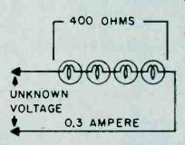
Fig. 10. Although problem looks different the basic circuit is same as
that for Fig. 9.
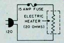
Fig. 11. Formula needed here is different since current is unknown. Just
look for triangle in Fig. 8 that has I shaded.
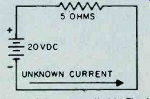
Fig. 12. Basic circuit is same as that in Fig. 11. Although three factors
are given, current is unknown quantity.
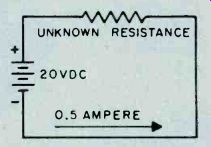
Fig. 13. Most Ohm's law problems are simple series circuits or can be reduced
to simple series circuits.
==============
Ohm's Law to Determine Voltage. Let's delve a bit more deeply into Ohm's law by applying it to a few cases where we want to determine the unknown voltage in an electrical circuit. Take a look at Fig. 9; which shows a simple series circuit consisting of a battery and resistor.
The value of this resistor is given as 200 ohms, and 0.5 ampere of current is flowing through the circuit. We want to find the value of battery voltage. This is easily done by applying Ohm's law for voltage as follows: E =I xR Let's go through this again, this time using a practical illustration. Fig. 10 shows a string of light bulbs, the total resistance of which is 400 ohms. You find that the bulbs draw 0.3 amperes when lighted. Let's say you would like to operate this string of bulbs from the standard 120-volt house current, but you don't know the voltage rating of the individual bulbs. By using Ohm's law for voltage, you, can easily determine the voltage to light the bulbs as follows:
(unknown voltage) = 0.3 (amperes) x 400 (bulb resistance) = 120 volts.
A word of caution. When cool, the resistance of a filament light bulb is much lower than when heated. As the filament is heated, the resistance increases due to positive temperature coefficient of the material as discussed earlier.
Ohm's law for current: I = I Ohm's Law to Determine Current. Now, let's take a look at a few examples of how to determine the value of unknown current in a circuit in which both the voltage and resistance are known.
Fig. 11 shows a series circuit with a battery and resistor. The battery voltage is 20 volts DC and the value of resistance is 5 ohms. How much current is flowing through the circuit? E R 20 (battery voltage)
5 (resistance in ohms)
I = 4 amperes You will note that the 15 ampere fuse will not blow in this circuit.
Again to get a bit more practical, let's take a look at Fig. 12. Here we see an electric heater element connected to the 120-volt house line. We know that this particular heater element has a resistance of 20 ohms when hot. The house current line is fused with a 15-ampere fuse. We want to know whether the heater will draw sufficient current to blow the fuse. Here's how to find this out by use of Ohm's law for current.
I= 120 (line voltage)
20 (Heater resistance in ohms)
I = 6 amperes
We find from the above use of Ohm's law for current that the heater draws 6 amperes, so it can he safely used on the line fused with the 15-ampere fuse. In fact, a 10-ampere fused line can also do the job.
Ohm's Law to Determine Resistance. Ohm's law for resistance enables us to determine the unknown value of resistance in a circuit. Fit. 13 again shows a simple series circuit with the battery voltage given as 20 volts and the current flowing through the circuit as 0.5 ampere. The unknown resistance value in this circuit is found as follows: Ohm's law for resistance: RR= E I 20 (battery voltage)
0.5 (current in amperes)
R = 40 ohms
Fig. 14 is a practical example of how to determine unknown resistance. Here, we want to operate a 6-volt light bulb from the 120-volt house line. What value of series dropping resistor do we need to drop the 120-volt house current down to 6 volts? The bulb draws 0.2 ampere when illuminated (hot). We must first determine the voltage which must be dropped across the series dropping resistor. This is done by subtracting the line voltage (120) from the bulb's voltage (6). This gives us a value of 114 volts which we use in conjunction with Ohm's law for resistance as follows:
R 114 (voltage drop)
0.2 (current in amperes)
R = 570 ohms
Resistance in Series. Many practical electrical and electronic circuits use two or more resistances connected in series. The point to remember in this case is that the total resistance is the sum of the individual resistances.
This is expressed by the formula: resistance of n number of resistances in parallel would be: R (total resistance) = R1 + R2 + R3 + etc.
...where R1, R2, R3, etc. are the individual resistances.
Thus, in Fig. 15 the total of the individual resistances is R (total) = 40 + 6 + 10 + 5 = 61 ohms.
Resistance in Parallel. Resistances may also be connected in parallel in a circuit as in Fig. 16. In this case the current flowing in the circuit will divide between the resistances, the greater current flowing through the lowest resistance. Also, the total resistance in the circuit will always be less than the smallest resistance since the total current is greater than the current in any of the individual resistors. The formula for determining the combined resistance of two parallel resistors is:
R (total) _ R 1 x R2 R1 + R2
Thus, in Fig. 16 the effective resistance of R1 and R2 is: 2x4 8 R (total) =or 1.33 ohms.
2+4 6
In a circuit containing more than two parallel resistors as in Fig. 17 the easiest way to determine the total circuit resistance is as follows: first, assume that a 6-volt battery is connected across the resistor network. Pick a value that will make your computations simple. Then determine the current flowing through each of the resistors using Ohm's law:
I = R
= = 3 amperes I = = 3 = 2 amperes I R3 6
= 1 ampere Next, add the individual currents flowing through the circuit: I = 2 amp. + 3 amp. + 1 amp.
I = 6 amperes.
Inserting this 6 amperes in Ohm's law, the total circuit resistance is found to be:
6 R=-=1ohm.
6 The combined equation for determining the total
1 1 + 1 + + 1 R Rl R2 R3 Rn
Quite often an electronic circuit will contain a combination of series and parallel resistances as in Fig. 18. To solve this type of problem, first determine the combined resistance of R2 and R3: R (total) 66 + i2-18 = 4 ohms.
This total value of R2 and R3 may be considered a single resistance which is in series with R1, and forms a simple series circuit. This simple series circuit is solved as follows: R (total) = 6 + 4, or a total of 10 ohms.
Power. The amount of work done by electricity is termed the watt and one watt is equal to one volt multiplied by one ampere. This may be expressed as: P = E x I where E = voltage in volts, I = current in amperes.
Also: E2 P= R and P=I^2R
As an example, assume that a toaster draws 5 amperes at an applied voltage of 115 volts. Its wattage would then be: P = 115 x 5 = 575 watts.
=========
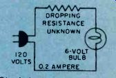
Fig. 14. his Ohm's law problem is somewhat more complex.
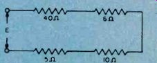
Fig. 15. Resistance in series is added. As far as voltage applied and current
flow is concerned the individual resistors are only one.
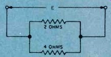
Fig. 16. Resistors in parallel are added algebraically-the result will
always be a value less than that of the lowest in the circuit.
==========
Magnetism and the Electron. The atom and a concept of its structure were a necessary preface to our discussion of basic electricity. By the same token, both are necessary to understanding basic magnetism.
As we've mentioned, electrons are in continual motion about the nucleus. The orbit is, in fact, a small loop of current and has a magnetic field that's associated with a current loop. In addition, experimental and theoretical investigation seems to indicate that the electron itself has a spin. Each electron, having its own axis, is a spinning sphere of electric charge. Electron spin, like the quantum and wave theories of light, is not so much a literal interpretation of a phenomenon as a useful concept that holds water when applied to the phenomenon of magnetism.
When the electron spins, the charge that is in motion produces a magnetic field. And, to briefly state the electronic explanation of magnetism, it seems that the magnetic properties of matter can be attributed to the orbital and spinning motion of the electrons comprising the atoms of the matter.
Millennia of Magnetism. Some of the basic principles and effects of magnetism have been known for centuries. The Greeks are credited as the ones who first discovered magnetism. They noted that a certain type of rock had the ability of attracting iron. Later, the Chinese noted that an elongated piece of this rock had the useful property of always pointing in a north-south direction when suspended by a string. This was the beginning of our compass.
This strange stone which intrigued people over the centuries is actually a form of iron ore known as magnetite. Not all magnetite shows magnetic properties.
Another name for the magnetic variety of magnetite is lodestone-the term lodestone being derived from two separate words, lode and stone. The term "lode" stands for guide, hence lodestone means "guide stone." All magnets, whether natural or manmade, possess magnetic poles, which are commonly known as the magent's north and south pole. As is the case of the electrical charges (which we studied earlier) between unlike magnetic poles and repulsion between like poles, it has been found that this magnetic attraction and repulsion force varies inversely as the square of the distance from the magnetic poles.
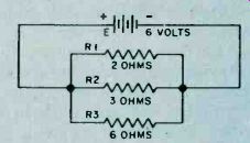
Fig. 17. Ohm's law can be used to determine the equivalent resistance of
two or more resistors in parallel. Total current-then solve for ohms.
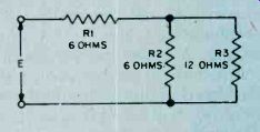
Fig. 18. Series-parallel circuit is not really difficult. Add R2 and R3
algebraically. Add effective resistance to R1 for total resistance.
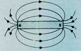
Fig. 19. Lines of force around bar magnet can be made visible by sprinkling
iron filings onto white paper over magnet. Lightly tap the paper and all
the filings will line up with the lines of force.
The Magnetic Field. We all know how a magnet exerts a force of attraction on a piece of magnetic material such as iron or steel. Also, when the north poles of two magnets are brought close together, they will try to repel each other, while there will be attraction between the north and south poles of two magnets. Although it is not clearly understood just what this force of magnetic attraction and repulsion is, it is convenient to visualize magnetic lines of force which extend outward from one magnetic pole to the other as illustrated in Fig.19.
Permeability. Magnetic lines of force can pass through various materials with varying ease. Iron and steel, for example, offer little resistance to magnetic lines of force.
It is because of this that these materials are so readily attracted by magnets. On the other hand, materials such as wood, aluminum and brass do not concentrate or encourage the passage of magnetic lines of force, and as a consequence are not attracted by magnets.
The amount of attraction a material offers to magnetic lines of force is known as its permeability. Iron and steel, for example, possess high permeability since they offer little resistance to magnetic lines of force. Nonmagnetic materials have low permeability. For practical purposes, we can say that reluctance is to magnetic lines of force what resistance is to an electrical current.
Electromagnetism. Any electrical conductor through which flows an electrical current will generate a magnetic field about it which is perpendicular to its axis as shown in Fig. 20. The direction of this field is dependent upon the direction of current flow, and the magnetic field strength proportional to the current strength. If this current-carrying conductor is wound into a coil, forming a solenoid, the magnetic field will be increased by each individual turn that is added. If an iron core is inserted in this current-carrying coil, the generated field will be increased still further. This is because the lines of force are concentrated within the iron core which has considerably less reluctance than the surrounding air.
The magnetic power of a multi-turn current-carrying coil through which a core is inserted is proportional to the current flowing through the coil as well as the number of turns in the coil. The current through the coil is termed ampere turns. As an example, if a coil consisting of 200 turns is carrying 2 amperes, its ampere turns equal:
Ampere turns = 200 turns x 2 amps.
Ampere turns = 400 ampere turns
Similarly a coil of 100 turns through which a current of four amperes flows also has 400 ampere turns.
Electromagnetic Induction. We saw earlier how a current-carrying conductor will generate a magnetic field which is perpendicular to the conductor's axis.
Conversely, a current will be induced in a conductor when the conductor is passed through a magnetic field.
The strength of this induced current is proportional to both the speed at which it passes through the field and the strength of the field. One of the basic laws pertaining to electromagnetic induction is Lenz's law which states: "The magnetic action of an induced current is of such a direction as to resist the motion by which it is produced." Fig. 21 illustrates two coils, A and B, which are placed in close proximity to each other. Coil A is connected in series with a switch and battery so that a current may be sent through it when, the switch is closed, and coil B is connected with a current-indicating DC meter. When the switch is closed, current will flow through coil A, causing a magnetic field to be built up around it. In the brief instant that the field is building up to maximum, it will "cut" the turns of coil B, inducing a current in it, as indicated by a momentary flick of the indicating meter.
When the switch is opened, breaking the current flow through coil A, the field around coil A will collapse, and in so doing will again induce a current in coil B. This time, however, the flow of current will be in the opposite direction. The meter will now flick in the direction opposite .to when the switch was closed. The important thing to remember is that the conductor must be in motion with respect to the magnetic field or vice versa in order to induce a current flow. You can perform this simple experiment using two coils made of bell wire wrapped around large nails, a few dry cells in series, and a DC zero-center scale meter.
Self Induction. As mentioned a short while ago, a magnetic field is built up around a coil at the application of current through the coil. As this field is building up, its moving lines of flux will cut the turns of the coil inducing a counter-electromotive force or counter-EMF which opposes the current flowing into the coil.
The amount of counter-EMF generated depends upon the rate of change in amplitude of the applied current as well as the inductance of the coil. This value of inductance is dependent upon the number of turns in the coil; a coil with many turns will have greater inductance than a coil with few turns. Also, if an iron core is inserted into the coil, the inductance of the coil will increase sharply. The unit of inductance is known as the Henry.
The Transformer. One of the most important and widely used applications of magnetic induction is the transformer.
Fig. 22 shows the basic construction of a typical transformer. While two separate windings are shown here, some transformers can have as many as five or six windings.
A transformer consists of two or more separate windings, electrically insulated from each other. One winding, known as the primary winding, is fed from a source of alternating current.
The alternating currents flowing through the primary induce a current in the secondary winding by virtue of magnetic induction. The transformer core is constructed from a relatively high permeability material such as iron which readily conducts magnetic flux between the primary winding and the secondary winding.
The alternating current flowing in the primary of the transformer produces a variation in the magnetic flux circulation in the transformer core which tends to oppose the current flowing in the primary winding by virtue of self-induction. The counter-EMF is just about equal to the voltage applied to the primary winding when no load is connected to the transformer's secondary winding.
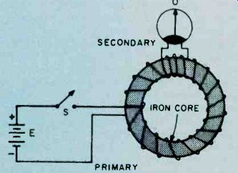
Fig. 20. Direction of flux lines is changed by direction of the current.
Heavy current is needed to make flux lines visible with sprinkled filings.
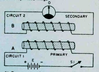
Fig. 21. Two-core transformer is inefficient since an air gap at either
end does not have permeability of a ferrous metal and some flux lines do
not go through core of secondary winding (B)-their effect is lost.
Fig. 22. Toroidal core is highly efficient but is very difficult to manufacture.
Familiar C- and E-shape core has less waste and windings are slipped over
the core. Efficiency is good-about 90 percent for most designs.
This accounts for the fact that very little current. flows through the primary winding when no load is connected to the. secondary. The negligible current that does flow under this no-load condition is known as the transformer magnetizing current. As the current drawn from the secondary winding increases, the primary current will increase proportionately due to the reduction in the counter-EMF developed in the primary winding of the transformer.
In any transformer the ratio of the primary to secondary voltage is equal to the ratio of the number of turns in the primary and secondary windings. This is expressed mathematically as follows: where
Ep = Es = Np = Ns = Ep Es = n1s primary supply voltage, voltage developed across secondary number of primary turns number of secondary turns
The above formula assumes that there are no losses in the transformer. Actually, all transformers possess some losses which must be taken into account.
Transformer Losses. No transformer can be 100 percent efficient due to losses in the magnetic flux coupling the primary and secondary windings, eddy current losses in the transformer core, and copper losses due to the resistance of the windings.
Loss of magnetic flux leakage occurs when not all the flux generated by current flowing in the primary reaches the secondary winding. The proper choice of core material and physical core design can reduce flux leakage to a negligible value.
Practical transformers have a certain amount of power loss which is due to power being absorbed in the resistance of the primary and secondary windings. This power loss, known as the copper loss, appears as heating of the primary and secondary windings.
There are several forms of core loss-hysteresis and eddy current losses. Hysteresis losses are the result of the energy required to continually realign the magnetic domain of the core material. Eddy' current loss results from circulating currents induced in the transformer core by current flowing in the primary winding. These eddy currents cause heating of the core.
Eddy current loss can be greatly reduced by forming the core from a stack of individual sheets, known as laminations, rather than from a single solid piece of steel.
Since eddy current losses are proportional to the square of core thickness, it is easy to see that the individual thin laminations will have much less eddy current loss as compared with a single thick core.
Another factor which effects eddy current loss is the operating frequency for which the transformer is designed to operate. As the operating frequency is increased, the eddy current losses increase. It is for this reason that transformers designed to operate at radio frequencies often have air cores and are void of ferrous metals.
Theory and Practice. We've come a long way from our initial discussion of the atom and its importance for an understanding of electricity and magnetism. And there's still a long way to travel to understand all about the subatomic nucleus and its satellites and how they are being harnessed in an ever-expanding electronics technology. But, we move ahead by mixing theory with practice-so, put your new knowledge to work in a project or two!
=======
Also see: