One tenth of a second to 99 hours. Both on and off times programmable. Manual or automatic operation resettable at any time.
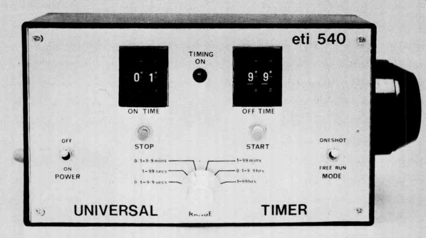

THE TIMING OF EVENTS and processes is becoming an ever increasing necessity particularly in applications involving automation.
Unfortunately most timers are either specifically made for a particular application - and difficult to adapt to others - or have restricted timing range, accuracy and facilities.
The ETI Universal Timer described in this project is free of most such constraints. It is extremely flexible, accurate and versatile. Its timing range is from 0.1 seconds to 99 hours.
Both 'on' and 'off' times can be programmed (for example 12 hours on and 47 hours off). It can be manually started, stopped, or reset at any time, can be set for automatic cycling or for single cycle operation.
It may be triggered by an external source ( light, sound or pressure transducer etc). Finally, as the unit is digital - the 50 Hz mains is used as the reference - timing accuracy is very high indeed, and a manual reset facility enables the timer to be synchronized with local time if so desired.
Clearly not all users will need all the facilities provided - so if the unit is required for a specific permanent use it is a simple matter just to leave out those ICs not required - several variations are described at the end of this project.
CONSTRUCTION
We strongly recommend that this unit be assembled using the printed circuit board shown.
Begin construction by fitting the links to the board as shown on the component overlay. Note that there are two points labeled 'a' and two points labeled 'b'. Link 'a' to 'a' and 'b' to ' b' using insulated hook-up wire routed on the copper side of the board.
Mount the resistors to the board followed by the diodes, transistors, capacitors and finally the ICs. Take particular care to ensure that all the polarized components are orientated correctly - especially the integrated circuits.
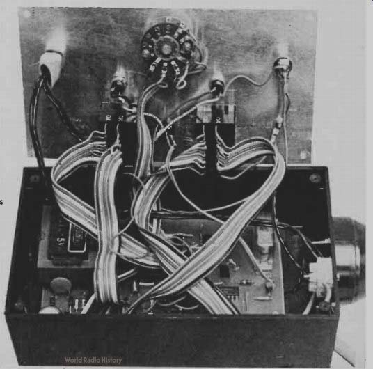
Wires should now be attached to the board for later connection to the front panel switches. We used rainbow cable for the connections to the thumb-wheel switches as this makes the wiring easier and also helps to keep the wiring tidy.
Mount the printed-circuit board into the case and mount the power outlet socket. Assemble the switches to the front panel and then interconnect the printed-circuit board, front panel and power socket in accordance with the interconnection diagram.
Finally after wiring the 240 Vac power circuitry insulate all 240 V terminals with tape to ensure that there is no risk of personal contact when fault finding is required at any later date.
CUSTOMIZING
The unit need not necessarily be built in its complete form and many different modifications are possible to lessen the cost of the unit when it is to be used for one particular application only. The modifications required for a number of specific applications are described below.
Specific fixed time - delete selector switches SW3 to SW6, and replace by wiring links from the appropriate outputs of IC4 and IC5 to the inputs of IC6/1 and IC6/2 respectively. The range switch may also be omitted by installing a link between the appropriate output of ICI to IC3 and pin 13 of IC4.
Single shot operation - connect both in puts of IC6/2 to ground and omit switches SW5 and SW6.
Timing 99 hours or less - omit IC3 and connect inputs of IC7/3 and IC7/4 to ground.
Timing 99 seconds or less - omit IC2, IC3 and IC7.
External triggering - simplest way is a relay contact in parallel with start or stop button.
The main consideration when making any changes is that the logic is CMOS and any unused inputs must be connected to ground or to + 12 volts to prevent damage to the IC (which may overheat with unconnected inputs).
------------------
SPECIFICATION ETI 540
MODES
Free-run On/off (note 1)
One shot Manual override ( note 2)
TIMING RANGE a l seconds to 99 hours (note 3)
ACCURACY
Mains synchronized OUTPUT 240 volts ac relay switched Note 1. Both on and off times are variable independently.
Note 2. Unit may be stopped or started at any time. If the appropriate button is pressed whilst in the same mode the timing is recommenced.
Note 3. Timing is adjustable by a common coarse control which gives ranges having a full scale of 9.9 seconds, 9.9 minutes, 99 minutes, 9.9 hours and 99 hours. Each range is adjustable from 1 to 99 that is one second on and 99 seconds off is possible whereas one second on and two minutes off is not ( different coarse range is required).
----------------
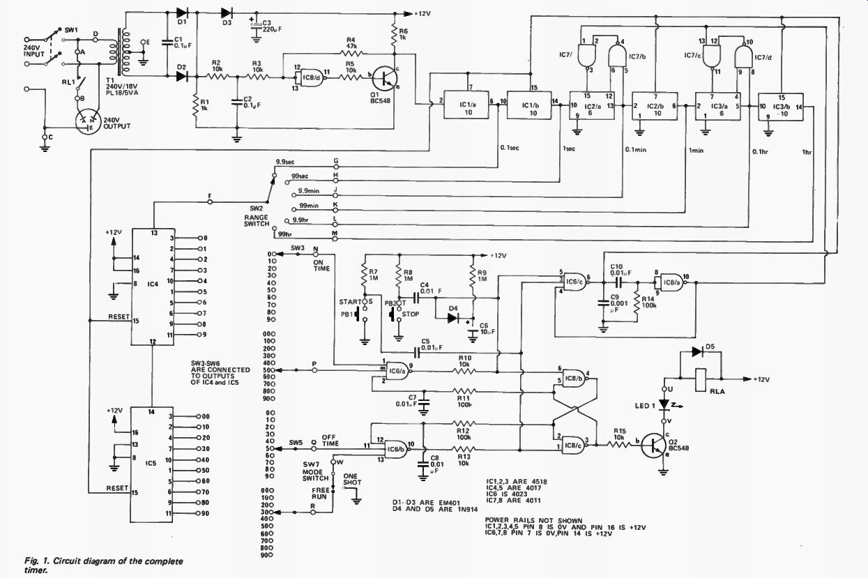
Fig. 1. Circuit diagram of the complete timer.
-------- IC1,2,3 ARE 4518 1C4,5 ARE 4017 IC6 IS 4023 IC7,8 ARE 4011
POWER RAILS NOT SHOWN IC1,2,3,4,5 PIN 8 IS 0V AND PIN 16 IS + 12V IC6,7,8 PIN 7 IS OV,PIN 14 IS + 12V
------------- HOW IT WORKS -- ETI 540
THE 240 Vac is reduced to 12 Vdc by transformer Ti and diodes D1 to 03.
Diode D3 isolates the smoothing capacitor C3 from the rectifiers and therefore 100 Hz ripple appears across R1. This waveform is used for the basic timing reference for the timer. To operate the counting ICs reliably a very fast rise- time waveform is required at the clock input. This is obtained by feeding the 100 Hz to a Séhmitt formed by IC8/1 and 01. Capacitor C2 is included to prevent the control tones superimposed on the mains for the control of hot-water services from upsetting the timing accuracy.
The 100 Hz from the Schmitt trigger is divided by 10 by Id/1 to give a 10 Hz or 0.1 second output - the first required. Note that due to the low frequencies involved from now on the outputs will be referred to as time periods not as frequencies. A second divide by ten stage is used to give a one second output. A division by six is then performed by 1C2/1 with IC7/1 and IC7/2 being used to decode the six count and reset the counter. This gives the one minute ( or sixty second) period required. Further divisions of 10,6 and 10 are used to provide the six outputs required to select periods from 0.1 seconds to one hour.
One of these six outputs is selected by the range switch SW2 and is fed to a 4017 IC - the first of a pair of decade counters which have ten decoded outputs. The ten outputs of each IC go high in turn for one clock period each.
As the two 4017 ICs are in series, a total division of 100 is obtainable. We have labeled the outputs of IC4 and IC5 as 0 to 9 and 00 to 90 respectively. IC4 is triggered by the clock enable as negative edge triggering is required. The second IC is clocked normally by the carry output from IC4.
We pause at this point to go straight to the control output which is via a relay RL1, this in turn being controlled by the flip-flop made up of IC8/2 and IC8/3.
This flip-flop can be controlled either manually by PB1 ( manual on) and PB2 (manual off) or automatically by 106/1 and IC6/2. To toggle the flip-flop automatically the output of either IC6/1 or IC6/2 must be low and for the output to be low the three inputs must all be high. This occurs only when the number selected by SW3 and SW4 (for IC6/1) and SW5 and SW6 ( for IC6/2) is held by the counters IC4 and IC5 and the third input from the flip-flop is used to ensure that the off-time of the relay is controlled only by the off-time selector switches. A small time delay is incorporated in the signal back from the flip-flop to avoid the ambiguity that could arise with equal times.
If the output of either IC6/1 or IC6/2 goes low the monostable formed by IC6/3 and IC6/4 is triggered and its resultant output is used to reset all the counters to zero. This reset also occurs if either of the manual push buttons is pressed. The push buttons are coupled into the logic by capacitors so that only the initial part of the press actuates the logic and there is therefore no dependency on the length of time for which the button is pressed.
The sequence of events is as follows assuming that initially the switches are set for 25 seconds on and 14 seconds off.
On first switch-on C6 ensures that the flip-flop is toggled into the off state and also that the counters are all reset to zero. The control inputs from the flip-flop to IC6/1 and IC6/2 are low and high respectively. Therefore until the flip-flop changes state only IC6/2 can have the three high inputs necessary to provide a low at the output. Meanwhile the counters IC4 and IC5 are counting up at the rate of one count per second.
After 14 seconds all three inputs to IC6/2 are high and the output goes low toggling the flip-flop. The monostable is then triggered and all counters are reset to zero. This removes the three high inputs to IC6/2 and the output goes high again. The pulse output of IC6/2 is very narrow and is about a microsecond long.
As the flip-flop has now changed state the relay has been closed and IC6/1 has been enabled ( control input to pin 2 now high). After 25 seconds all the inputs to IC6/1 are high and the same procedure as before resets the counters and changes the state of the flip-flop.
In the one-shot mode of operation one input of the off timer is grounded and the off time procedure is effectively disabled. The only way that the timer can now start is for the manual start button to be pressed.
-------------
-------------
PARTS LIST - ETI 540
Resistors R1 R2,3 R4 R5 R6 R7- R9 R10 R11.12 R13 R14 R15 1 k 10 k 47 k 10 k 1 k 1 M
- 10 k
- 100 k 10 k 100 k 10 k
Capacitors C1 C2 C3 C4,5 C6 C7,8 C9 C10
Diodes D1- D3 D4, 5 LED 1
• 1A1 "
0.1 µF 50 V disc ceramic
0.1 uF polyester 220 / IF 16 V electro
0.01 uF polyester 10 µF 16 V electro
0.01 µF polyester
0.001
0.01 uF " EM401 or similar IN914 or similar R L4850 or similar Transistors
01,02 BC548 or similar Integrated Circuits IC1-1C3 -- 4518 IC4,5 4017 IC6 4023 IC7,8 4011 Transformer 240 V/18 V CT PL18/5 VA pc Board ETI 540 Relay, single pole 280 n coil 240 V 5A contact Switches SW' SW2 SW3-6 SW7 PB1,2 double pole toggle switch single pole 6 position rotary single pole 10 position • single pole toggle single pole -make- push buttons
C&K 321100000 is a 2 section Thumbwheel switch forming SW3 + 4 and SW5 + 6 (2 required)
Case plastic 196 x 113 x 60 mm power cord, plug and clamp 3 pin power outlet socket
----------
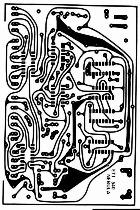
Fig. 3. Interconnection diagram.
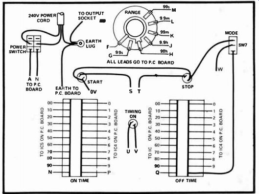
Fig. 4. Printed-Circuit board layout for the timer. Full size 153 x
100 mm.
GR. SHOULD EQUAL LDR RESISTANCE AT OPERATING POINT (COULD BE VARIABLE)
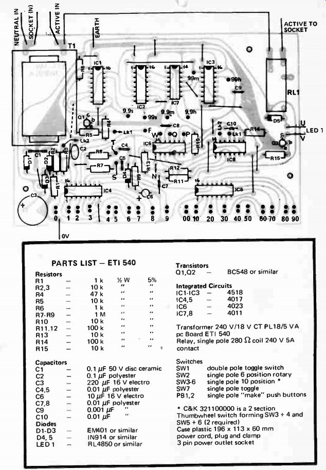

Fig. 5.
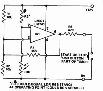
Fig. 6. For triggering timer from a change in light level this circuit
will be found suitable.
Scotchcal front panels for the Universal Timer are available from Electronics Today for $4.00 - plus a self-addressed stamped envelope at least 120 mm x 200 mm. The panels are 109 mm x 190 mm.
Please make checks payable to: 'Scotchcal Offer', Electronics Today International, 15 Boundary Street, Rushcutters Bay, NSW, 2011.
-----
-----
ad
Electronics Today International 4600 and 3600
SYNTHESIZERS
Here are full plans for building two full-scale electronic music synthesizers.
Many thousands of these remarkable units have been built world-wide since the series of constructional articles started in Electronics Today late in 1973.
Since then, the two units have gained a reputation as being among the most flexible and versatile of electronic instruments available.
They have been built as school and university group projects, by recording studios, professional musicians, university music departments and as home hobby projects.
Here, the complete series has been reprinted in a completely corrected and up-dated form.
The book is available in a limited edition of 2000 copies only.
ENSURE YOUR COPY NOW!
Send S12.50 to Electronics Today International, 15 3oundary Street, Rushcutters I - 3ay NSW, 2011.
----------