This Section describes representative frequency standards for radio frequencies and audio frequencies ; these devices are sources of signals against which the calibration of other devices is checked. During the past 20 years, noteworthy progress has been made in frequency standardization methods, especially in the transition from time-honored crystal-type primary standards to the atomic type. Many new devices have appeared; so the survey here must necessarily be selective.
The distance we have traveled in frequency standardization is evident when it is noted that 50 years ago the absorption wavemeter was the accepted frequency-checking instrument, and for the standardization of this device the Bureau of Standards could say in its 1924 book Radio Instruments and Measurements: "The most direct method for the wave length calibration of a standard or commercial wavemeter is a comparison with a high-frequency alternator. From the speed of the machine and the number of poles or other structural data the frequency of alternation can be computed directly. The range of such alternators is, however, limited ; the usual construction does not furnish a wave length shorter than 3000 meters." The widespread need to measure frequency accurately is underlined by the fact that every type of electronics person, from the casual amateur to the sophisticated research engineer includes some sort of frequency standard among his essential equipment. The complexity of the standard is, of course, a function of the accuracy and stability required of it.
4.1 CLASSIFICATION OF STANDARDS
There are two classifications of standards of all kinds: primary and secondary. A secondary standard is one that derives its accuracy from having been calibrated against an even more dependable device, a primary standard. The primary standard is a device that needs no comparison with any other source based upon the same kind of units of measurement. Primary standards are noted for high precision and high stability. Primary standards usually are stationary; secondary standards may or may not be portable.
Secondary frequency standards are widely distributed and are usually found in laboratories, shops, stations, and schools.
Primary standards, on the other hand, being costly and often bulky and usually requiring specialized professional attention, generally are found only in universities, government facilities, and advanced laboratories. Secondary standards are brought to them for calibration. Secondary standards often have lower long-term stability than primary standards do, being used primarily for relatively brief time intervals and subject to frequent recalibration against a primary standard. While it is true that some secondary frequency standards have elaborate provisions for temperature control and voltage control and may demonstrate long-term stability, they nevertheless remain in the category of secondary standards because they must be checked against a primary standard.
Whereas a secondary standard must be checked against a primary standard of the same sort (i.e., a secondary frequency standard must be checked against a primary frequency standard) , a primary standard is checked against some fundamental physical quantity or may need no checking at all. Thus, a crystal-type primary standard may be checked against sidereal time ; and the atomic-type primary standard, being controlled directly by the constant resonant frequency of certain atoms, needs no checking at all.
4.2 CRYSTAL-TYPE PRIMARY STANDARD
This device is based upon a highly precise quartz-crystal oscillator. High stability in this oscillator is obtained by employing a special low-drift quartz plate, closely regulating all operating voltages, closely controlling ambient temperature of the entire oscillator, controlling humidity, safeguarding against excessive vibration, and minimizing loading of the oscillator.
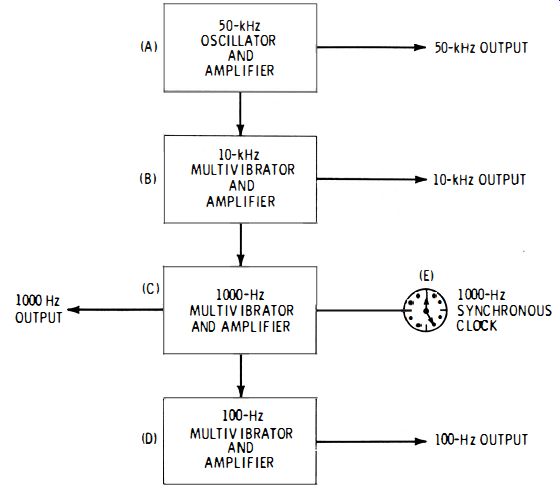
Fig. 4-1. Crystal-type primary standard.
Fig. 4-1 shows a functional block diagram of this device. In this arrangement, the crystal oscillator (A) operates on 50 kHz and is followed by a buffer amplifier for isolation. The output of this stage contains harmonics 50 kilohertz apart far into the radio spectrum. The oscillator synchronizes a 10-kHz multivibrator and amplifier (B), and the output of this latter stage provides a 10,000-Hz signal with harmonics 10 kilohertz apart reasonably far into the radio spectrum. In succession follow synchronized multi vibrator/amplifier stages for 1 kHz and 100 Hz (Stages C and D, respectively), which provide outputs of 1000 Hz and 100 Hz. From the diagram, it is seen that the multivibrators divide the oscillator frequency by 5 (Stage B) , 50 (Stage C) , and 500 (Stage D) , each output having the same accuracy as that of the oscillator. The output of the 1000 Hz multi vibrator/amplifier (C) drives a 1000-Hz synchronous clock. Any drift of the oscillator frequency may be detected when the time indicated by this clock is compared with standard time, and the oscillator frequency then is corrected (by means of fine tuning, adjusting of operating voltage and temperature, or all of these). Sidereal time can be measured with great precision by using the methods of astronomy. The clock keeps correct time as long as the oscillator frequency is exactly 50 kHz (50,000 vibrations of the quartz plate are required for each second indicated by the clock) ; accordingly, frequency error may be determined in terms of the number of seconds by which the clock leads or lags correct time at the periodic checking instant. A frequency accuracy of the order of 1 part in 10 million, or better, is common for this type of primary standard.
For instance, the system could start with a 100-kHz oscillator, and multivibrators can be provided at frequencies other than, or in addition to, those shown, to provide af, as well as rf checking frequencies.
Recent custom regards this device as a highly refined secondary standard, since it must be referred to an external quantity-standard time-for calibration. We retain the original classification here, however, since some of these devices are still in service in their original role, that of primary standards.
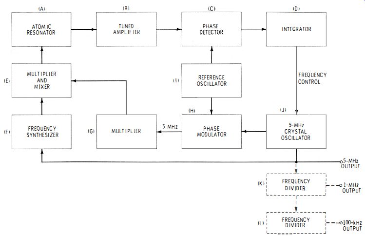
Fig. 4-2
4.3 ATOMIC-TYPE PRIMARY STANDARD
Work with masers led to the discovery of natural resonance in atomic systems, such as a beam of cesium atoms, and to the epochal observation that this frequency is one of the most constant quantities in Nature. The phenomenon is explained by the fact that when stimulated particles fall to a lower energy level, they radiate energy of constant frequency (approximately 9192 MHz for cesium). The action is initiated by injecting microwave energy at the natural frequency of the atoms, to stimulate them. When the atoms fall back to a lower energy state, they radiate energy at their constant natural frequency.
The next logical step was to utilize this phenomenon as a primary standard of frequency. With an atomic resonator as the basis, the result is a true primary standard, since no outside quantity need be referred to-the authority is self-contained, the atomic resonance of the atom.
Fig. 4-2 shows a functional block diagram of the essential arrangement of a cesium primary frequency standard (Hewlett-Packard Model 5061A). In this standard, the atomic resonator (A) embodies a cesium-beam tube in which cesium atoms travel through a microwave cavity. In the tube, the beam intensity is varied by a phase-modulated signal which sweeps through the atomic ' resonance frequency. This signal is generated by a 5-MHz crystal oscillator (J) and is phase-modulated, frequency-multiplied, and otherwise processed by G and E.
The output of the resonator is amplified (Stage B) and, through phase detector C and integrator D corrects the frequency of the crystal oscillator. This oscillator thus may be described as an atomic-resonator-controlled oscillator operated in a phase-locked system.
The crystal oscillator (J) supplies the 5-MHz output of the standard and may be applied to frequency dividers, such as K for 1 MHz and L for 100 kHz. A synchronous clock, operated from an atomic-type primary frequency standard, indicates correct time with high precision.
The accuracy of this standard is specified as ±1 x 10^-11.
The first cesium-beam frequency standard was introduced by Hewlett-Packard in 1964. The cesium unit is now accepted through
out the world as the definitive primary standard.
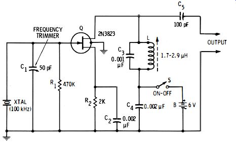
Fig. 4-3. 100-kHz crystal oscillator.
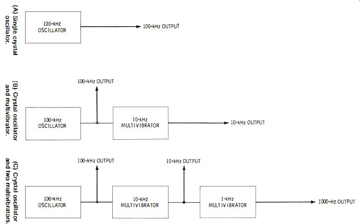
Fig. 4-4
4.4 CRYSTAL-TYPE SECONDARY STANDARD
The frequency spotter, described in Section 3.15, Section 3, is the simplest form of secondary radio-frequency standard.
It is also the commonest secondary standard. It is found in many versions, from simple to sophisticated, as complete units and also as components of other systems such as receivers, heterodyne frequency meters, and rf signal generators, and is supplied both in factory-built and kit types. This device usually is a fairly simple 100-kHz crystal oscillator.
Fig. 4-3 shows the circuit of a FET-type 100-kHz oscillator suitable for use as a secondary frequency standard. Here, the adjustable inductor (L) is slug-tuned for maximum output.
Trimmer capacitor C1 shifts the crystal frequency by a very small amount, allowing the oscillator to be adjusted against a primary standard. Similar circuits employ bipolar transistors, vacuum tubes, or ICs. While the 100-kHz frequency is popular, other standards employ 50 kHz, 1000 kHz, or 5 MHz.
Fig. 4-4 shows three common versions of the secondary standard. Fig. 4-4A is the single crystal oscillator described above. In Fig. 4-4B, a 10-kHz multivibrator has been added to provide 10,000-Hz output and harmonic check points. In Fig. 4-4C, 10-kHz and 1-kHz multi-vibrators both have been added to the oscillator to provide 10,000-Hz and 1000-Hz check points, respectively. Multivibrators at other frequencies also may be used. Each stage may be followed by a buffer amplifier for isolation and signal boosting, if desired. Also, a filter is sometimes connected in each external output when low-distortion outputs are desired on 100 kHz, 10 kHz, and 1 kHz.
The accuracy and stability of the crystal-type secondary standard depend upon (1) type of crystal, (2) temperature control, (3) operating-voltage regulation, and (4) recency of calibration. If a low-drift crystal is used without temperature control and voltage regulation, the frequency may be expected to be constant within 0.005 % at ambient temperatures between zero and 50°C, following calibration by adjustment of C1 (Fig. 4-3 ) for zero beat with a primary standard. Better performance may be expected when temperature and voltage are controlled.
4.5 ATOMIC-TYPE SECONDARY STANDARD
Like the primary standard described in Section 4.3, a secondary standard also can exploit the property of atomic resonance.
The basic arrangement of an atomic-type secondary standard is essentially the same as that of the similar primary standard (see Fig. 4-2). In the secondary standard, however, rubidium vapor, rather than cesium, is employed as the atom source.
Variations in the pressure of the buffer gas that is required with rubidium cause small variations in the atomic resonant frequency, and these necessitate that the instrument be checked periodically against a primary frequency standard. Hence, the rubidium-type unit is categorized as a secondary standard.
The rubidium secondary standard nevertheless offers superb stability and is superior to a stabilized, crystal-type secondary standard. Representative stability of the rubidium unit is ±1 x 10-11 per month.
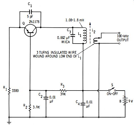
Fig. 4-5. Self-excited secondary standard.
4.6 SELF-EXCITED SECONDARY STANDARD
In unexacting measurements, a self-excited 50-kHz or 100-kHz oscillator sometimes will suffice as a secondary frequency standard. Most such oscillators have good stability at such low frequencies when they are solidly constructed, operated at low power, and lightly loaded.
Fig. 4-5 shows a bipolar-transistor-type, 100-kHz oscillator that can be used as a secondary frequency standard. The tuning slug of the 1.08- to 1.8-mH inductor (L1) is adjusted for zero beat with a primary standard (usually a standard-frequency transmission picked up with a radio receiver ). Similar oscillators may employ a field-effect transistor, integrated circuit, or vacuum tube.
The self-excited unit is reliable only during, or immediately after, calibration. Like all self-excited oscillators, this circuit is subject to an unpredictable amount of drift, as well as abrupt frequency shifts that result from mechanical shock, body capacitance, and operating-voltage changes.
In the same light, a radio-frequency signal generator tuned to 50 kHz, 100 kHz, 1 MHz, or 5 MHz and pre-calibrated from a frequency standard makes a good self-excited secondary standard. Such a generator usually contains a low-drift circuit and often voltage regulation. As a secondary standard, the generator suffers, however, from low-voltage output. But a number of generators have an auxiliary 1-volt "high-output" terminal, and a signal of this amplitude is satisfactory for most frequency-standard uses. It should be noted, too, that the output of a good signal generator is a reasonably pure sine wave and accordingly lacks the harmonics that are so useful in using a frequency standard. However, the 1-volt output can be distorted by passing it through an external circuit containing a germanium diode biased into its most nonlinear region, and this will provide some harmonics.
4.7 STANDARD-FREQUENCY BROADCASTS
The National Bureau of Standards radio stations WWV ( Colorado ) and WWVH ( Hawaii ) transmit standard frequencies continuously day and night, and these signals may be used for the calibration of frequency standards and other equipment. WWV transmits on frequencies of 2.5, 5, 10, 15, 20, and 25 MHz; WWVH transmits on 2.5, 5, 10, 15, and 20 MHz. Both stations modulate all of their carriers with standard audio frequencies of 400, 500, and 600 Hz, each tone being maintained for 45 seconds. A 440-Hz tone is used at other intervals. The National Bureau of Standards also broadcasts a 60-kHz signal via Station WWVB ( Colorado). The accuracy of the transmitted frequencies is maintained by a cesium-type primary standard (see Section 4.3) and is kept within ±2 parts in 100 billion.
For a full description of this service, see NBS Special Publication 236, NBS Frequency and Time Broadcast Services (25 cents, Superintendent of Documents, U. S. Government Printing Office, Washington, D.C. 20402 ).
4.8 RADIO STATIONS AS EMERGENCY STANDARDS
When no other source is available, a radio broadcast station can serve as an emergency frequency standard, since these stations are required to maintain their carrier frequencies within a few hertz. The procedure is to zero-beat the fundamental or a harmonic from the secondary standard under test (or other device) with the carrier of the station.
The greatest difficulty of this method is the inability to recognize zero beat accurately while the carrier is modulated with the station's program material. In the station's zeal to fill every second on the air, there is almost no break in music or talk. But, with patience, the operator will be rewarded (though infrequently) with a blank carrier.
4.9 AUDIO-FREQUENCY STANDARDS
Standards are available also for precise audio frequencies.
These are discussed below.
A. Conventional frequency standard.
Some of the frequency-divider stages of a primary or secondary radio-frequency standard deliver precise audio frequencies.
Thus, in Fig. 4-1, 10 kHz, 1000 Hz, and 100 Hz are available ; and in Fig. 4-4C, 10 kHz and 1000 Hz are available. Other audio frequencies may be obtained from either standard by means of suitable multi vibrators with or without filters.
B. Low-frequency crystal oscillator Special crystal oscillators are available down to 2000 Hz.
These units have excellent frequency and drift characteristics.
Typical frequency accuracy is ±100 ppm at 25°C ; typical stability is ±0.005 % from 0 to 50°C.
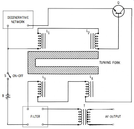
Fig. 4-6. Tuning-fork oscillator.
C. Tuning-fork oscillators
A tuning fork machined precisely for a desired frequency can be maintained in vibration by a transistor or tube circuit, and audio output may be picked up from the fork. The resulting oscillator can serve as an audio-frequency standard, especially if its temperature and operating voltage are closely stabilized.
Fig. 4-6 shows one version of the fork-controlled oscillator.
Here, the driving coils (L1 and L2 ) and the pickup coils (L3 and L4 ) are wound on permanent magnets placed close to opposite tines of the fork. They do not touch the fork, so they do not cause mechanical restraint of the vibrations. Harmonic distortion is minimized by the filter and the degenerative network.
Commercial tuning-fork oscillators are available for frequencies from 1 Hz to 100 kHz, with an accuracy as good as 1 ppm. These units are compact, compared with some of the fork oscillators of past years that employed massive forks. The efficacy of modern subminiature tuning forks is evident from the performance of electronic watches driven by them ; such a timepiece, actuated by a 1000-Hz fork, can show an error of only a minute or two per month.
D. Standard-frequency stations
As explained in Section 4.7, audio frequencies of 400, 440, 500, and 600 Hz are available as modulation on standard-frequency signals broadcast by the National Bureau of Standards on Stations WWV and WWVH. These signals have high accuracy.
These frequencies can also be heard via a telephone call to the National Bureau of Standards. Dial (303 ) 499-7111 ( Boulder, Colorado ).
E. Audio signal generator
A laboratory-type sine-wave audio signal generator providing discrete frequencies, rather than continuously variable tuning, is usable as a secondary audio-frequency standard, within its limitations of accuracy and drift. Such instruments can supply several thousand push-button-selected frequencies.
The frequency span is typically 10 Hz to 1 MHz. Frequency accuracy is ±0.2 0/0 , and frequency drift is of the order of 10 ppm/minute.
A good, continuously tunable audio signal generator, operated in conjunction with a digital-type audio-frequency meter (see Section 2.5, Section 2) to indicate the frequency, performs well as an audio-frequency standard. Here, the frequency accuracy is that of the digital counter. When in use, the generator can be regularly reset to correct any drift.
These sine-wave generators produce a very-low-distortion signal, so that no harmonics of useful amplitude are available.
But, when the generator has square-wave as well as sine-wave output, the square wave will supply strong, odd-numbered harmonics.