AMAZON multi-meters discounts AMAZON oscilloscope discounts
Although probes used in radio and TV servicing have many different names, most of them fall within a few categories. This would include such units as demodulator probes, divider and high-voltage probes. However, there are numerous types which have a special application and as such do not fit into any regular classification. Included in this group we would have the audio tracer, hum, capacitor tester, frequency-compensated and a.f., r.f. tracer probes, magic-eye probes, etc.

Fig. 801. Simple audio tracer probe checks signal at any point after the detector.
Value of capacitor in probe is not critical.
Audio-tracer probe
This probe permits tracing audio signals at any point beyond the sound detector stage in AM. FM and TV sets. As you can see from the illustration (Fig. 801) it is simply a .01-µf capacitor in series with a shielded cable.
The output of the probe can be put into a pair of earphones, v.t.v.m. or scope. A modulated r.f. signal, fed into the front end of the receiver, will result in a steady audio signal at the input to the measuring instrument. If you depend on a radio or TV station for a signal source, the varying audio voltage will cause the v.t.v.m. needle to swing or will show as a changing waveform on the face of the scope tube. The audio-tracer probe is often used in con junction with a simple audio amplifier. You do not even require a separate audio amplifier for this purpose. Just connect the out put leads of the audio probe to the center and either end terminal of the volume control of any receiver in good working order.
Using the probe
In trouble shooting, start at the output of the audio detector and work your way toward the voice coil of the speaker. A dead or weak stage or one that is not working properly can be found very easily. If, for example, you have a good signal at the control grid of one of the audio amplifier tubes but no signal when the probe point is put on the plate pin, that particular tube circuit is dead. If you have the same amount of signal, or less, at the plate than you have at the control grid, then the tube may be weak. If the signal is clear and undistorted at the input to a tube but has hum or distortion when the probe pin is at the plate, then trouble exists in that circuit.
Use the probe to check coupling capacitors. If the signal exists on the plate side of the coupling capacitor but you hear no signal on the other side (control grid of the following tube), then the capacitor may be open or the grid circuit may be shorted. You can check for intermittent coupling capacitors in the same way. Put the probe pin on the control grid connected to the coupling capacitor. Wiggle the capacitor gently or tap it with an alignment tool. If the sound breaks, the capacitor is intermittent.
The capacitor in the probe blocks d.c., allowing the audio signal through. You can place the probe at any point that has audio signal or audio plus d.c. voltage. For best results the capacitor should be a mica type and should be rated for at least 600 working volts d.c. The value of capacitance is not critical. Any unit, .01 µfor greater, can be used. The probe housing should be of metal to avoid pickup of stray fields. An insulated length of shielded wire should be connected to the probe head. Connect the shielded braid of the wire to the metal housing of the probe.
The center conductor of the shielded wire or cable connects to one side of the capacitor inside the probe. The other side of the capacitor is connected to the probe tip. The probe tip and the capacitor must be carefully insulated from the metal housing or the shield braid of the cable. Fasten a wire to the front end of the probe and solder an alligator clip to the other end of this wire.
This will be the ground connection of the probe.
Hum probe

Fig. 802. This probe is very useful for tracking down sources of hum. Use
any small diameter, insulated wire for the coil.
Finding hum or tracing hum to its source can easily be one of your most exasperating experiences when working with radio, audio or TV. The probe shown in Fig. 802 is very useful for locating hum in all types of receivers or audio systems.
Jumble wind as many turns as you can conveniently get on a powdered-iron slug. The slug can be any spare you may have salvaged from an old i.f. transformer or r.f. coil. When you finish winding, cover the coil with rubber tape. Any size of wire can be used. The type of insulation on the wire is not important. However, the more turns of wire you get on the slug, the greater will be the sensitivity of the unit, hence small diameter wire is preferable. Bring the two ends of the coil through a probe handle about 12 inches long. The probe handle can be bakelite or plastic tubing, but it should be covered with metal shield braid. Connect the coil leads to flexible coaxial cable. Put a connector at the end of the cable suitable for connecting to the vertical input of your scope.
Using the hum probe
Connect the leads of the probe to the vertical input of the scope. One lead (either one) should go to the vertical and the other lead to the ground post. Set the vertical gain and vertical sensitivity controls to maximum. Pick up the probe handle (near the cable end) and then examine the scope screen. If the horizontal line on the screen seems wavy, turn down the vertical gain slowly until the line is straight. Now put your fist around the probe coil. Your scope should show a rather large but distorted, sine wave. This is 60-cycle hum pickup.
The probe is now ready for action. You can touch it to a chassis to determine the amount of hum voltage at a particular point, examine magnetic fields around transformers and chokes as well as determine the effectiveness of shielding. The probe coil will not be harmed if you touch the slug (protruding from the coil) directly to the chassis or any metal-cased transformer or choke.
Capacitor-tester probe
A probe of special design and construction is available to help the service technician locate open and intermittently open capacitors. To prevent the temporary healing of intermittent capacitors when they arc checked, this probe includes a variable resistor which is operated by the probe tip.
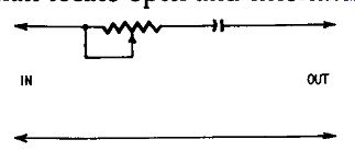
Fig. 803. Circuit diagram of capacitor tester probe.
A circuit diagram of the probe is shown in Fig. 803. In Fig. 804 we have a cross-sectional view showing mechanical construction details. The needle point of the probe is spring-loaded, the amount of resistance present in the probe depending upon the pressure you place on the probe needle point. When the probe is touched very lightly to a test point, the probe has maximum resistance.
With a small amount of pressure the probe point is pushed back into the body of the probe, reducing the resistance. A portion of the inside of the probe is coated with graphite and is the resistance element. This resistance is made variable by means of a sliding contact which is connected to the probe needle. As the sliding contact is pushed toward the rear end of the probe (by pressure placed on the probe needle point), the amount of resistance in the probe unit decreases to a minimum.
The probe is used with the radio or TV set turned on and actually in an intermittent condition. This is important, since intermittent capacitors often will heal temporarily when a radio or TV set is turned off for testing and then back on again. This temporary healing is serious problem for the service technician, since the capacitor becomes almost impossible to locate and yet must be replaced if callbacks are to be kept to a minimum.
This probe makes a positive test. Normal operation of the radio is restored when the defective capacitor is tested. The set gradually goes back into the intermittent condition as pressure on the probe is reduced. Tests can be made rapidly. No adjustments or capacitance settings are needed. It is not necessary to unsolder capacitors for testing.
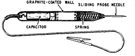
Fig. 804. Cross-sectional view of capacitor-tester probe.
How capacitor-tester probe works
When an intermittent capacitor is tested with this probe, temporary healing of the intermittent is prevented by the high initial resistance in the probe unit. This allows the test capacitor in the probe to charge slowly, preventing a heavy current flow and voltage drop. As the probe tip is pressed, the resistance gradually drops to zero and the probe then becomes a substitution tester.
The resistance automatically returns to maximum for the next test when the probe is removed.
Sometimes, in servicing, a known good capacitor is used to shunt a suspected defective unit. An uncharged capacitor is al most like a short circuit, and the instantaneous current can be very high in a circuit where the potential is as low as 200 volts d.c. This large current has a welding effect on paper capacitors.
Since such capacitors tend to become intermittent at or near the points where the foil connect to the leads, the current, by its welding action, produces a temporary cure. Thus, the disadvantage in testing with a substitution capacitor is the healing effect of the sudden, heavy current flow in the intermittent capacitor caused by the charging of the test capacitor at the instant it is applied. This charging surge also causes a sharp voltage drop and a disturbance that can travel all through the circuit the capacitor is in and to other sections of the radio or TV set where it can temporarily heal any capacitor that is intermittent.
Servicing with capacitor-tester probe
Turn on the radio or TV set and note the abnormal operation, such as the whistle caused by an open bypass capacitor. Allow the set to operate until it stops or else goes into the intermittent condition. Localize the defective stage or section by using a typical signal-tracing technique.
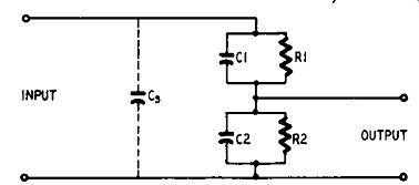
Fig. 805. Electrical arrangement of the frequency-compensated probe.
Having found the defective stage, connect the test probe across each of the capacitors in turn. Do this by attaching 'the clip to the ground or outside foil side of the capacitor and then pressing the probe tip against the terminal to which the other lead of the capacitor is soldered. Try not to move the capacitor under test.
Avoid applying the probe directly to the leads of an intermittent which seems to be sensitive to the slightest movement or vibration. If possible, trace back a distance on the other leads going to the same terminals as the capacitor and apply the probe at these points. If a capacitor is soldered to a terminal of a wafer tube socket, apply the probe to the corresponding tube pin ex tending under the socket. This will prevent moving the capacitor as it is tested.
The capacitance of the test capacitor within the probe (.05 µf, 600 working volts d.c.) is an ideal value for substitution testing across practically all bypass and coupling capacitors. Do not use it on capacitors working above 600 volts, such as buffer capacitors of auto radios, shorted capacitors or low-value units which are part of tuned circuits (these are usually mica or ceramic types which seldom give the intermittent trouble experienced with paper capacitors.)
The important point to remember in repairing intermittents is to avoid healing any capacitor which might be intermittent, until it is positively located.
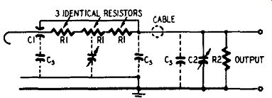
Fig. 806. Circuit diagram of the frequency-compensated probe.
Frequency-compensated probe
One of the most common specialized probes is the frequency compensated type (Fig. 805) used to prevent distortion of TV signals tapped off high-impedance points and fed to the input of a scope. The unit consists of two parallel-connected R-C networks in series across the signal source with the output signal tapped off at the junction of the R-C networks. Distortion is minimum when R1-C1 equals R2-C2.
The tip and body of the probe are shielded to minimize pickup of hum and stray signal voltages. Although the shield is designed for optimum performance, it adds to the stray input capacitance c. and brings the total value to 10-15 µµf. This capacitance greatly attenuates the signal (20 db or higher) and often is high enough to detune high-impedance circuits or distort video-frequency signals. When a capacitance type probe is used with a wide-band low-gain scope, the technician must be constantly aware of the amount of attenuation and possible distortion in his instrument.
The circuit arrangement of a frequency-compensated probe is shown in Fig. 806. The high input capacitance, usually caused by the probe shield, is reduced by using C1 as the shield around the hot input lead. This results in the greatest portion of stray capacitance C. being shunted in parallel with the cable capacitance. The body of the probe houses R1-three 1.5 -meg-ohm resistors in series-shunted by a small gimmick capacitor. The out put voltage of the probe is developed across R2.
Probe amplifier
A wide-band video amplifier is used to compensate for the high attenuation in the probe (40 db). The amplifier circuit, shown in Fig.807, has enough amplification to overcome the losses in the probe, so that the over-all gain, from probe input to amplifier output, is I. In other words, your scope will then see a signal of the same amplitude as that presented to the probe tip. The low output impedance of the video amplifier prevents signal distortion that normally occurs when the scope has a high input impedance shunted by high cable capacitance.
The unit has a built-in selector for attenuating the input signal by 10 and 100 to prevent possible overloading of the video amplifiers. The scope is usually operated at maximum gain with the attenuator in the wide-band amplifier set for the lowest out put that gives adequate vertical deflection. Thus any possible circuit overloading will occur in the scope where it will be more readily recognized and can be corrected by reducing the scope's gain.
The portions of the compensating circuit equivalent to C2-R2 (in Figs. 805 and 806) are a part of the attenuator. The input stage is a 6U8 with its pentode section connected as a shunt-peaked video amplifier and its triode section as a direct-coupled cathode follower. The second stage is a 6AH6 with shunt peaking in its plate circuit. A 1-meg-ohm variable resistor in the grid circuit is the low-frequency compensation adjustment. The output stage is a 12BY7 cathode follower with an 80-ohm output impedance. B plus voltages are regulated by a 3-tube voltage-regulator circuit using a 12B4 series regulator, 12AX7 control tube and a 5651 voltage-regulator tube to supply the reference voltage. The heaters of the 6U8 and 6AH6 are supplied with d.c. voltages developed by a I-amp bridge rectifier across the heater winding of the trans former.
Specifications for the probe and amplifier are: over-all gain, X1, X0.1, and X0.01; bandwidth, 5 cycles to 12 mhz ± 3 db; input impedance, 4.5 megohms; input capacitance, 1.5-2 µµf; maximum input voltage, 150 a.c., 600 d.c.; undistorted output, 4.5 volts maximum.
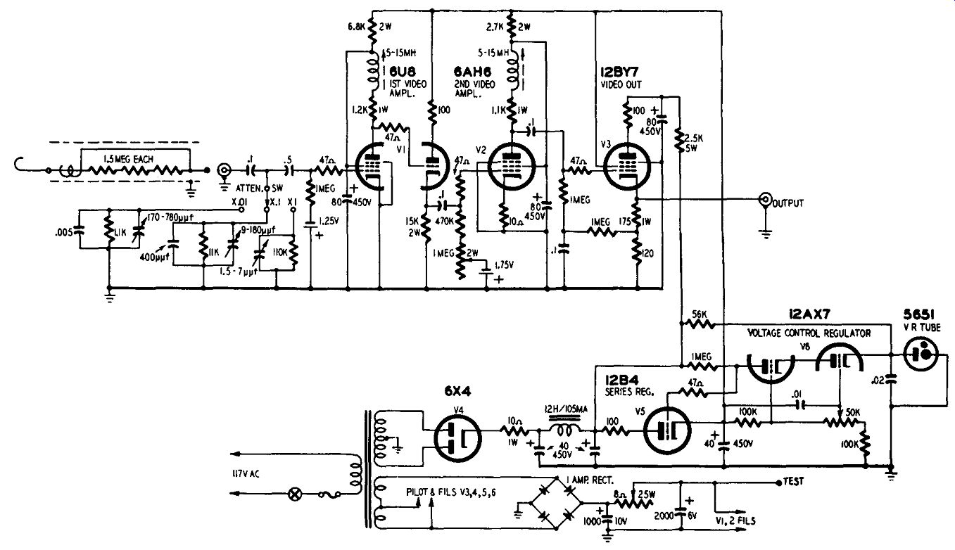
Fig. 807. The frequency-compensated probe is used in conjunction with a wide-band
video amplifier. The amplifier compensates for the high attenuation of the
probe.
A.f. and r.f. tracer probe
Here is a compact and useful tracer that can be constructed for less than $5. It may be carried in your pocket or in a small tool box. The circuit diagram appears in Fig. 808 and its construction is shown in Fig. 809.
This unit works on either a.f. or r.f. When in use on a.f., the reactance of the r.f. choke is negligible, so R1 becomes the load.
With r.f. applied, the choke becomes the load, with R1 being by passed, as shown in the schematic. A1 N 34 or a 1N66 germanium diode can be used as a detector.
A plastic cigarette case houses the unit. Assemble all the components, except the test probes, outside of the case, using just their own leads for support. Then bring the probe and ground leads through the top cover of the case, and solder them in place.
Now slide the assembled unit into the case, and bring the jack out through the hole at the bottom. You can make these holes with ease using the heated tip of a large nail. Have the openings on the top cover large enough to allow sliding the cover off along the wires for possible repairs.
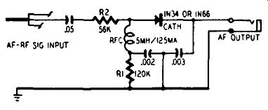
Fig. 808. Schematic diagram of the compact a.f.-r.f. tracer probe.
Using the probe
To use, connect the ground clip to the ground side of the receiver, or the chassis on a.c.-d.c. sets. Plug in a pair of high-impedance phones or feed the probe's output into an audio amplifier.
With the receiver tuned to a local station, start at the antenna and pick up the r.f. signal. Then move on to the r.f. amplifier tube (if any) or the i.f. convertor. Touch the grid lug and then the plate lug. Do this to each tube in the following order: the i.f. amplifier, second detector, a.f. amplifier, and the power amplifier (output tube). Never apply the probe to the rectifier tube!
Whenever the signal is not heard, you will know that the trouble is in that particular section of the receiver. If the signal is traced from the antenna to the output tube without losing it, check the speaker transformer for a defective winding.
The probe will not show the exact nature of the trouble, but will narrow it down for easier servicing. Then you can use your meter in that particular section for locating the defective tube or part.
The components used in the tracer probe are not critical in value, but they should approximate those shown in the schematic.
Since the probe will be applied to the plates of tubes the 0.05-µf blocking capacitor should have a voltage rating of about 600.
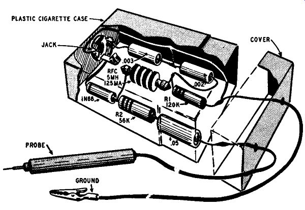
Fig. 809. Physical layout of the components in the a.f.-r.f. tracer probe. Parts
placement is not critical.
This is especially true when the probe is used to trace the horizontal and vertical sweep voltages in a television receiver. In some sets the boost voltage is used as the plate supply of the vertical and horizontal circuits, and it often exceeds 500 volts.
When servicing TV sets be careful not to touch the probe to any point having pulse voltages higher than 500 volts peak.
Miniature test probes
In this guide we have been primarily concerned with probes used for radio and television servicing. However, electronics is by no means confined to repair work, many technicians finding employment in such varied enterprises as hearing aids, radar, development and research in laboratories, electronic production in factories, manufacture and maintenance of computing devices, etc. Regardless of the type of work, wherever test instruments are used you will find the need for probes. While such probes are made to fit specific testing problems, the information given in this guide should enable you to use such probes with a greater degree of understanding.
As examples of such specialized probes, consider the two types of miniature test probes recently devised at the National Bureau of Standards. These probes were designed to speed development and testing in the NBS radar miniaturization laboratory.
Light and compact, the probes are designed to cling to the test point without danger of contacting adjacent leads. Intended particularly for use with miniaturized electronic equipment, the probes offer possible advantages for use with conventional-sized devices as well.
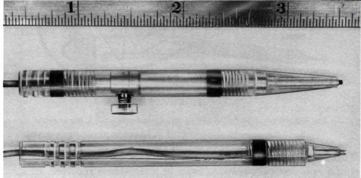
Fig. 810. Two types of miniature test probes. The ruler shown at the top of
the photograph will give you some idea of the actual size of the probes.
The two probes are illustrated in Fig. 810. The probe shown at the bottom of the picture is a push-on type with a very small tapered jaw that is simply pressed onto the wire under test. The jaw is of hardened beryllium copper, silver-plated for good electrical contact. It grips the wire with a slight spring action until sufficient pull is exerted to remove it. While service technicians often use crocodile or alligator type clips at the tip end of the probe for gripping purposes, such clips are too bulky and unwieldy for servicing in crowded spots of radio and TV sets. If you make your own probes, you will find that the use of a push-on type jaw can be very convenient. However, no matter which type of clip action you use, you will find that being able to fasten your probe into place will release your hands for work elsewhere-adjusting your test equipment or servicing.
The jaw of the probe shown in the lower part of Fig. 810 screws into an insulating handle made of lucite (plastic) or similar non-conducting material. The probe handles shown in the illustration are ¼ inch in diameter and 3-½ inches long. Only about 1/16 inch of the metal jaw protrudes from the insulating handle, so that the danger of shorting to nearby components is minimized.
The other probe, shown immediately below the ruler in Fig. 810, is a lock-on type so designed that it cannot be removed from the wire until a release button on the side of the probe is pressed. A small hook mechanism at the end of the probe remains open only while the button is pressed and tightens on the wire Fig. 811. This picture shows the miniature probes at work. These probes have the advantage of compactness but lack of shielding limits usefulness.
when the button is released. In other respects, including size, the lock-on probe is similar to the push-on model. Like the push on model, the lock-on probe is designed to accommodate wires varying considerably in diameter. In Fig. 811 we see how both probes are put to work checking components in a diminutive 8 tube i.f. amplifier.
R.f. indicator probe
This probe is very useful for detecting oscillation in the r.f. stages of small transmitters, boosters for TV, etc. A simple r.f. detector probe like that shown in Fig. 8 I 2 is helpful in detecting weak r.f. oscillations. The probe circuit is untuned so it will be easier to use, but this does reduce its sensitivity. The pickup coil of the probe may be three or four turns of self-supporting wire with an inside diameter of about I inch. Smaller diameter coils can be wound to meet your particular needs.
Although in the illustration we show the use of a d.c. meter having a full-scale deflection of 200 microamperes, a meter having greater sensitivity would be more desirable. The function of the capacitor across the meter is simply to bypass any r.f. and to keep such currents out of the meter. The value of capacitance is not critical. Since the voltage c1.cross the meter will be very small, you need not concern yourself with the working voltage rating of the capacitor. If, in making tests, you find that the meter needle tends to swing in the wrong direction (toward the left) either reverse the connections to the meter or reverse the connections to the germanium diode. Do not do both.
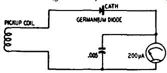
Fig. 812. R.f. detector probe circuit.
The probe works on the principle of electromagnetic induction.
It will help you locate open or shorted coils. The probe can be used only with the radio or TV set turned on. The coils that you test with this probe must be unshielded. The usefulness of the probe can be increased by having not one but a group of pickup coils, each having a different number of turns. You can wind these coils so as to slide over the end of a plastic rod. If you will mount a pair of spring clips on the plastic rod, you will be able to connect and disconnect the pickup coils quite easily.
R.f. voltmeter probe
The usual procedure for measurement of r.f. voltages is to use an r.f. probe and a v.t.v.m. However, there will be times when you will wish to test for the presence of r.f. without too much concern for the actual amount of voltage present. While you can use your v.t.v.m. and r.f. probe for this purpose, the sensitive r.f. voltmeter probe described here is extremely convenient. It is ready to operate instantly and requires no connection to the power line. It isn't even necessary to have a ground connection as body capacitance is enough to provide a return path. But for safety's sake it is best to ground it, especially if there is high voltage d.c. around. Where d.c. is present in the circuit an external blocking capacitor is necessary.
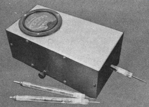
Fig. 813. Photo of the trim-looking unit and the associated plug-in multiplier
probes. The positioning of the meter is not critical and may be turned to suit
your con11enience. An inexpensive 0-1 ma meter is used.
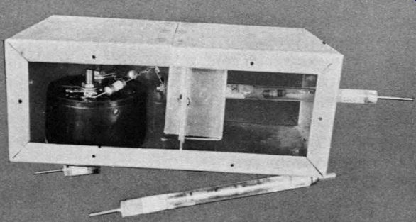
Fig. 814. View of the inner construction showing placement of the components.
The metal box consists of two shielded compartments. Both sides of the metal
housing are held in place by self-tapping screws. The entire probe is readily
accessible for any repairs or changes you might wish to make.
Originally built for amateur use, this probe (see Fig. 813) can be used to measure relative values of the voltage (with a more sensitive meter and a higher voltage multiplier) at the plate of horizontal output tubes or high voltage rectifiers in TV sets. The meter should present about the same load as the picture tube and the filter capacitor.
The popular germanium diode probe used for measuring r.f. voltage is usually limited to 30 volts maximum, as more than this might exceed the back voltage rating of the crystal, especially if the waveform is not a sine wave. Some crystal diode rectifiers can be used up to 150 volts, and with a capacitance type multiplier will safely read almost any voltage.
The unit described here has been used for quantitative tests on transmitters and open-wire feeder lines to antennas. The illustration, Fig. 814, shows that the case is used as a three-section shield-two sections around the probe which is also the multiplier, and one around the meter and rectifier assembly. The shield around the probe must have a low capacitance to the resistors or some of the current will pass directly to ground without registering on the meter. The multiplier must be shielded to prevent the sensitive low-voltage end of the multiplier from picking up r.f. both from the source and from the high-voltage end through distributed capacitance. The two-section box shield does this with out introducing too much capacitance to ground. The capacitive effect is minimized further by using a fairly large meter current.
A 0-1-ma meter is used but the over-all sensitivity is about 450 ohms per volt. This does load the circuit somewhat but for transmitting work this is not undesirable. The probe circuit is shown in Fig. 815.
The case is constructed of 52S½H aluminum sheet. This alloy combines stiffness and workability. For an 8 x 4 x 3-inch case, sheeting of .025 gauge is about right, The sides, however, could be heavier since it isn't necessary to bend them. One side is riveted permanently and the other one is fastened with self-tap ping screws. Two partitions reinforce the sides, shield the multi plier, and divide the case into three sections. The construction of the inner shields and banana jack support should be completed before assembling the case.
The multiplier resistance for each range may be determined by using an audio-frequency voltage and an accurate a.c. voltmeter.
Start with about 450 ohms per volt. The multipliers would be accurate only for sine waves as most voltmeters read r.m.s. values.
The multiplier should have at least three resistors, especially for the higher ranges. On the 1,500-volt range the resistors may dissipate a little over 3 watts so the total wattage should be adequate.
It is preferable to have the resistors in a multiplier as identical as possible in wattage and ohmage.
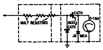
Fig. 815. Circuit diagram of the diode-type voltmeter.
The probe-multipliers are made of Amphenol polystyrene tubing and rods. ¼-inch rods just fit into ¾-inch tubing, so these sizes are used. A ½-inch length of rod is drilled axially and tapped for the 6-32 thread of standard banana plugs. It is difficult to drill this straight unless the rod is placed in the drill chuck and the drill bit clamped in a vise. This rod is then cemented in the end of a piece of tubing with polystyrene cement and allowed to harden. Then a 1 / 16-inch hole is drilled alongside the threads for the resistor lead. After the resistor string is made up, use a length of 1/16-inch brass welding rod at one end for the probe tip. The resistors should be so spaced that about half of the last one will be inside the inner shield when the probe is plugged in.
After making a final check of the multiplier for accuracy, seal the probe end with a section of rod drilled to fit the welding rod, and cement it in place.
The meter illustrated uses four probes to give 0-3, 30, 300 and 1,500-volt ranges. The circuit was selected ·because it gives linear readings on all but the 3-volt scale, allowing d.c. meter scales to be used. A 1 N 35 dual crystal (having matched characteristics) is used in preference to the 1N34 types.
Materials for voltmeter
One 0--1-ma meter, one .01-µf mica capacitor, one 1N35 germanium crystal, some ¼-inch polystyrene rods, several lengths of ¾-inch polystyrene tubing 5½ inches long, several piece of brass welding rod, several banana plugs, a jack with insulating washers, three matched 1-watt 5% tolerance resistors (see text), per multiplier-probe, and solder. Several .025-gauge 52S½H aluminum sheets, binding posts, hardware, etc.
Probe holder
Many modern radio and TV sets are made so compactly that it is difficult to hold the probe in place by using a standard-size alligator clip fastened to the probe tip. You can overcome this difficulty by making a simple gadget which works as well.
The adapter is made from a contact out of a molded octal socket. Remove the whole contact and make a narrow slit in the eye. Now slide the contact over the end of your test probe. When checking circuits, signal tracing, etc., slip the eye of the contact adapter over the circuit wire and give the probe a slight twist to hold it in place. The illustration (Fig. 816) shows how the adapter is used.
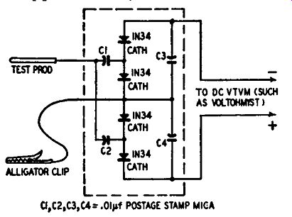
Fig. 817. Circuit diagram of the quadrupler probe. The probe is very useful
for making tests in circuits having very low r.f. voltage.
Quadrupler probe
The probe circuit shown in Fig. 817 is unusual in that it has an a.f.-r.f. voltage-quadrupler arrangement. Voltage step-up is obtained without a transformer. The d.c. output voltage of this probe is equal to approximately 5.66 times the r.m.s. value of the input voltage. This results in much increased meter sensitivity.
For example, the full-scale deflection on the 0-3-volt d.c. range of the v.t.v.m. will indicate an a.f. or r.f. input voltage of only 0.53 volt r.m.s. when this probe is used.
Although the voltage-quadrupling probe uses four IN34 crystals and four .01-µf postage-stamp mica capacitors, it may be built into a small-sized container. The crystal polarities indicated must be followed or the circuit will not multiply correctly.
It is advisable to make an individual voltage calibration after the probe has been completed and plugged into the d.c. vacuum tube voltmeter, since the rectification efficiency of production lot crystals varies and the 5.66 multiplication factor might not hold exactly for a particular quartet of crystals.
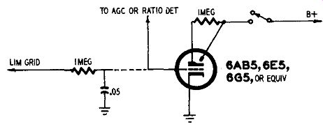
Fig. 818. Circuit diagram of magic-eye probe.
Magic-eye probe
With the a.g.c. systems included in present TV sets, the picture contrast changes very little for large changes in input signal. Therefore, it is difficult to adjust indoor antennas, outside rotating beams or TV boosters, for best results. This magic-eye probe can be used when you want maximum input signal.
The probe consists of an electron-ray indicator tube. The choice of tube is not critical. You can use any of the types mentioned in the circuit diagram (Fig. 818). To build the probe, obtain a section of tubing having a length of about 4-½ inches and a diameter of 1-½ inches, approximately. The tubing can be plastic, bakelite, aluminum or any material you have on hand.
The indicating face of the magic-eye tube should extend slightly from one end of the probe housing while the probe tip is mounted at the other end. You will need to bring two leads into the probe, one for B plus and the other for one leg of the filament line.
These voltages can be obtained quite readily from the TV set you are working on. The two wires, filament and B plus, should terminate in shielded alligator clips which can then be attached to the desired filament and B plus voltage points in the TV set.
You can mount the magic-eye tube in a socket or solder directly to the pins of the tube. The cathode of the tube should connect to one side of the filament. From this pin run a wire through the probe housing. This wire, about 8 inches long, will be the ground wire of the probe.
Using the magic-eye probe
If the set uses a ratio detector, touch the probe point to the negative end of the electrolytic capacitor in the ratio-detector circuit. If the set uses a limiter-discriminator circuit, the probe point should go to the grid of the first limiter through a filter network as shown in the diagram.
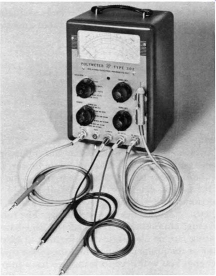
Fig. 819. Modern test instrument showing a complete set of probes.
If there are two positions of minimum shadow close together, this means that the sound i.f. is over-coupled. Then the correct tuning position is between the two.
Plugs and connectors
Some test instruments come supplied with a complete set of probes for just about every use. A typical example of this is shown in the photo (Fig. 819). However, it is entirely possible that your v.t.v.m. or scope did not come supplied with probes, in which event you may wish to buy or build your own. If you decide to build a probe, you must make some arrangement for connecting the probe to your scope or v.t.v.m.

Fig. 820. Fastening a coaxial cable to a jack.
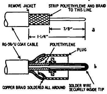
Fig. 821-a,-b. Illustration at top (a) shows preparation of coaxial cable
while lower illustration (b) shows how to solder the cable to the plug.
If your scope uses binding posts, the problem of connecting the probe is quite simple. Wrap a single turn of tinned wire around the exposed shield braid of the coaxial cable. Solder the wire to the braid. The inner lead of the coaxial cable (the so called hot lead) is usually fairly thin wire. Solder a tiny clip to this wire. Now wrap the end of the cable with Scotch tape. To make a connection to your scope, insert a 1-inch length of bare, tinned wire into the vertical binding post. When you use the probe, the clip connected to the hot lead of the coaxial cable should be fastened to this wire. The wire previously soldered to the shield braid of the cable should be connected to the ground binding post of the scope.
If you do not observe these precautions, you will soon find that constant flexing of the center conductor of the coaxial cable will cause it to break.
A much better arrangement is to have the probe cable terminated in some kind of coaxial connector or plug. However, even with such connectors, your coaxial cable must be electrically and mechanically secure.
A coaxial cable going into a jack such as a PL-54, PL-55, PL-68 or JK-26 should be anchored to eliminate strains on the connections. The result of the special clamping bands manufacturers use can be duplicated easily. The way in which this is done is shown in Fig. 820. After connecting the cable, wrap the clamping area with No. 20 or 22 solid wire. Then twist the two ends tightly together and apply a small spot of solder. The twisting of the ends gives a strong clamping action.
See Fig. 821 for the technique to be followed in soldering to a coaxial plug. First, remove the vinyl jacket, copper braid and polyethylene insulation as shown at a in the illustration. Be careful not to nick the braid or center conductor. Solder the connections as shown at b. Line up the cable with the body of the plug, then use a hot iron for soldering.
Tinning or soldering a wire to the shield braid of coaxial cable will cause the underlying plastic to melt and can result in a short between the center conductor and the outer braid. Prevent this by putting a piece of metal sleeving under the braid at the soldering point. Remove the sleeving after the soldered connection has been made. If you find it difficult to get the metal under the braid, push the braid back slightly and it will expand enough to allow the sleeving to be used. Work rapidly to avoid excessive heat which will damage the polyethylene insulation, thus increasing leakage. Excessive heat can also cause a short circuit between the inner conductor and the shield braid.
No matter which type of connector you use, always check it with an ohmmeter. In making this test, flex the coaxial cable with the ohmmeter leads going across the plug. The meter needle should show an open circuit condition and should not move. The cable connected to your probe should be treated carefully. Do not roll it into tight loops. If the cable should kink or knot, straighten it before using it.
Neon-bulb probe
A tiny neon bulb such as the NE-2 or NE-51 can be used as a probe. You do not have to make any connections. There are no wires going to the bulb, and the probe does not require the use of any test instruments whatsoever. There is no circuit diagram for the probe since there is no circuit. Simply count the neon bulb at the end of a plastic tube about 12 inches in length. The inside diameter of the plastic tube should be approximately equal to the diameter of the neon bulb. If the neon bulb will not fit into the plastic tube, ream the inside of the plastic tube with the blade of a pen knife. The N E-2 has a pair of leads coming out of the bottom of the bulb. Snip these off. The NE-51 has a bayonet type base and requires no attention on your part.
Put a small dab of Duco cement inside the plastic tube, insert the neon bulb, allow a few minutes of drying time and that's all there is to it. Your probe is ready for action.
Using the neon-bulb probe
This probe is used to test for the presence or absence of high voltage in a TV set. Bring the bulb end of the probe close to the plate cap of the horizontal output tube. If the output tube is working properly, the neon bulb will glow. No connections are necessary. With a weak horizontal output tube, the neon bulb may glow weakly or not at all.
You can also use this probe to test horizontal output trans formers. Put the probe near the plate cap of the high-voltage rectifier tube. If the horizontal-output transformer is working, the neon bulb will glow.
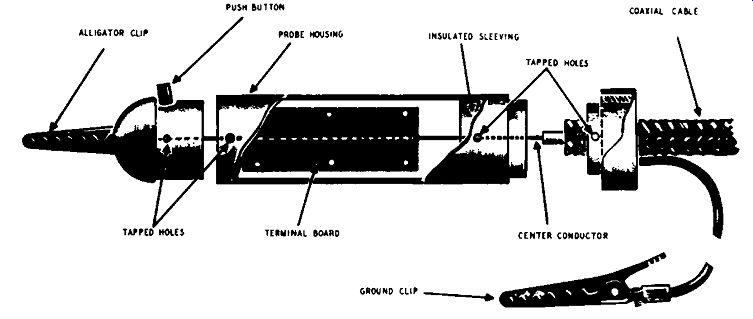
Fig. 822. Drawing of a well-constructed probe housing. Component parts can
be mounted on both sides of the terminal board. Pressing down on the flush-/button
opens the jaws of the alligator clip.
Probe housing
The kind of housing that you can make for your probe is limited only by your own skill, ingenuity and the kind of tools you have at your disposal. A good probe has certain desirable mechanical characteristics. It should not be so bulky that it would be too awkward to hold. The probe housing, if made of metal, should have some form of insulating material wrapped around it to prevent accidental shorting when working in close quarters in a radio or TV set. The probe should be sturdy enough so that it will not be damaged in regular use. The cable going in to the probe must be mechanically secure. The components inside the probe-resistors, capacitors, crystals, or tubes-should be securely mounted, permitting the probe to be used in any position. The assembly of the probe should be such that you can take it apart easily in the event of damage to one or more of the electrical components or if you wish to make some changes or replacements.
Choice of a probe tip depends upon the user. Some technicians prefer a needle point for the probe, others prefer a point with a clip-on action.
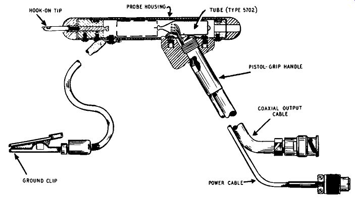
Fig. 823. Pistol-like structure of the cathode-follower gun probe. A rotating
hook on tip is a unique feature.
A typical probe housing is shown in Fig. 822. Here an alligator clip is used to hold the probe into place. Pressing down on the push button opens the jaws of the clip, releasing the probe.
The probe head is held on to the probe housing by means of a set screw rotated into a pair of tapped holes. You can substitute a needle point for the alligator clip, but for holding purposes you will still need some sort of fastening device if you want the probe to stay in place while you work.
Cathode-follower gun probe
One of the reasons for the great popularity of gun-type soldering irons, aside from their ability to heat rapidly, has been their construction in the form of a gun. Apparently, a tool with a gun handle is favored by many technicians.
This type of housing is now being used in the manufacture of probes. The probe assembly is shown in the drawing of Fig. 823. Its small fountain-pen size and pistol-grip construction make it especially convenient to handle. Connection to the scope is made through a 5-foot cable supplied with a BNC type connector and to its power supply through a 5-foot miniature power cord and locking type connector. The tip of the probe is so designed that it can be hooked onto a circuit test point and rotated a full 360° while in use, if desired. The insulated ground clip should be located as close as possible to the signal point.
A cable support is provided for use with the probe so that both hands of the user can be made free to record observations or make adjustments of equipment. After the probe is hooked to the circuit under observation, a loop of the cable may be passed in and out of the opening in the probe support; the stiffness of the cable will hold the probe in position. For certain high-frequency applications, the response of the probe may be improved by either ( 1) shortening the length of the flexible ground lead or by replacing it with a short length of flexible braid or (2) shortening the coaxial cable.
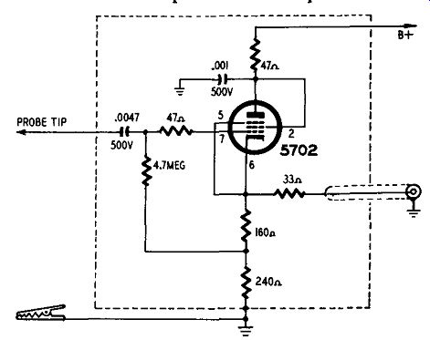
Fig. 824. Circuit diagram of the cathode-follower probe.
A circuit diagram of the probe is shown in Fig. 824. The bandwidth of the probe is 5 hz. to 14 mhz; maximum signal input is 5 volts peak-to-peak. The approximate gain of the probe is 0.7.
This is typical cathode-follower operation and means that for every 1 volt into the probe, the output is 0.7 volt. Since the probe attenuates the input signal approximately 30% , to make quantitative measurements from the plastic scale on your scope, using the probe, special calibration must be therefore performed. To do so, connect the probe to a known peak-to-peak calibration voltage. Adjust the scope gain controls to produce the selected deflection. This can be done in the manner described on page 83 of this guide.
When using the probe across a high-Q tuned circuit, a 1,200 ohm ½-watt composition resistor should be connected in series with the probe to prevent oscillation.
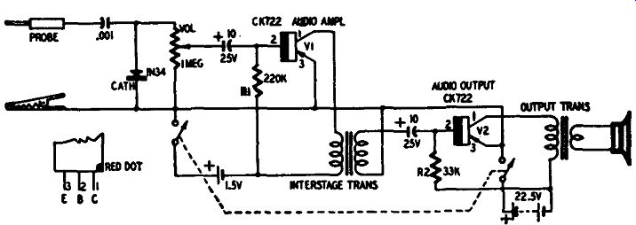
Fig. 825. Circuit diagram of the pistol-type transistor probe. The unit is
completely self-contained.
Transistor probe
This little transistorized signal tracer resembles the pistol-type soldering iron used by many service technicians. It is compact and has only one outside lead-an alligator grounding clip. The pointer of the tracer is touched to the circuit being tested; the signal is rectified, amplified, then reproduced through a 2-inch speaker. The circuit diagram is shown in Fig. 825.
A .001-µf disc type capacitor couples the incoming signal to the amplifier. A 1 N 34 crystal rectifies any r.f. signal picked up and feeds it to a volume control. The volume control is a standard type but a midget unit could have been used. Had that been done, the d.p.s.t. switch could have been placed on the control instead of at the top of the unit.
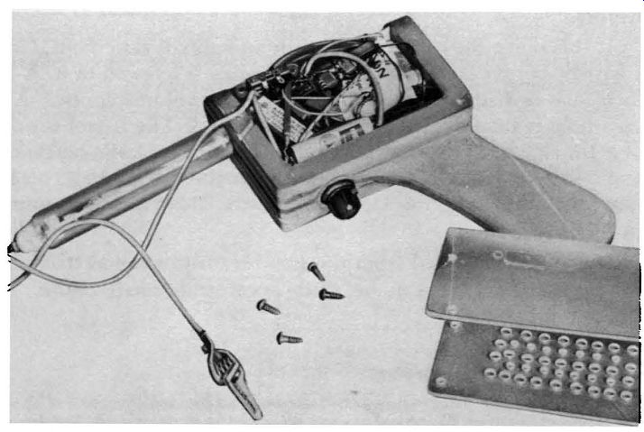
Fig. 826. Assembly of the transistor probe. The plastic cover, held on by
four wood screws, has a large number of drilled holes which act as a speaker
grille.
A midget electrolytic capacitor couples the incoming signal to transistor V1. Both transistors are CK722's, mounted in hearing aid tube sockets. Regular sockets can be used. Be careful when wiring the leads because heat from a soldering iron can easily damage transistors. A good trick is to let long-nose pliers absorb the heat. This also applies to the IN34.
R1 is a base return and develops bias for this stage. Since transistor characteristics vary, choose R2 for the value that provides maximum volume within the applied current limits. To find the correct value, use a 500,000-ohm potentiometer in place of R1 and vary it for maximum signal. Also connect a milliammeter in series-the current should not rise higher than 5 ma. The, a.f. stage is transformer-coupled to the output stage. This little unit is a Stancor UM-113 : primary impedance 20,000 ohms, secondary impedance 1,000 ohms, designed primarily for transistor amplifying stages. A standard interstage transformer could be used if the signal tracer is constructed on a chassis where space is not limited. A 10-µf electrolytic couples the signal to the base of V2. The base-return resistor R2 was measured before being placed in the circuit just as R1 was. A small output transformer feeds the amplified signal into a 2-inch speaker.
When wiring be sure the transistors are properly connected and that neither one draws more than 5 ma. The wiring is not critical but all leads and components must be closely spaced with the leads as short as possible. There isn't any separate chassis, the two transistor sockets being soldered to the speaker frame. Pins 3, 4, and 5 of the hearing aid sockets are soldered together. A heavy piece of brass wire is soldered to both sockets and then anchored to the 2-inch speaker frame. The positive lug on the 22.5-volt hearing aid battery is also soldered to the 1-inch bolt fastened to the speaker frame. When plugging the transistors into their sockets, be sure both red dots or pins are plugged in properly.
A d.p.s.t. push type switch is mounted on top.
Construction of the gun holder is easy. See Fig. 826. Get a few scraps of three-ply wood and draw a gun on each piece. On two of the pieces cut off the handle. Place the other piece between these and glue and nail them together. After the assembly dries, round the edges, carve and sand, giving it the appearance of a pistol. The middle section of the pistol is not sawed or cut out until the plastic is formed around it.
Lucite is used as a cover. It is fitted around the pistol assembly while heat is applied from a gas flame. Hold the plastic away from the flame. Then the plastic can be formed around the gun assembly and held there until it sets. The speaker holes can be drilled before or after the plastic is bent. All protruding corners are cut and rounded off to fit snugly around the wooden assembly.
At this point the center of the gun assembly is sawed out. Only a narrow border is left and the plastic piece is screwed to it. A ¼· inch hole is drilled into the bottom for the volume control. A 1 inch hole is then drilled for the pistol barrel. The barrel consists of a 1-inch piece of round plastic tubing with a plastic bottle cap and 2-inch bolt fastened into the end as the test probe. To save space the small coupling capacitor and the 1N34 can be mounted in the plastic tube.
The results obtained from the small transistor signal tracer are surprising. Troubles can be easily located in small radios, TV sets and amplifiers.
Parts for transistor probe
1-33,000, 1-220,000 ohms, resistors; 1-1 megohm, potentiometer; 1-.001 µf ceramic disc capacitor; 2-10 µf, 25 volts, electrolytic capacitors (small as possible); I-interstage transformer, primary impedance 20,000 ohms, secondary impedance 1,000 ohms (Stancor UM-113 or equivalent); 1--output transformer, primary impedance 2,000 ohms, secondary 3.2 ohms (Stanco, A-3332 or equivalent); 2-hearing-aid or transistor sockets; 2-CK722 transistors; 1-sheet of plastic; 3-pleces of 3-ply plywood; 1-2-inch speaker; 1--d.p.s.t. switch (see text); 1-1N34; 1--alligator clip; 1-plastic tubing; 1-22.5-volt hearing-aid battery.
AMAZON multi-meters discounts AMAZON oscilloscope discounts