If you're going to get seriously involved with electronics, you're going to have to buy or build some kind of electronic test equipment. The project team describe what types of test gear you need.
ANY READER seriously intending to test, trouble shoot, modify, design or experiment with electronics projects will need some kind of test gear (electronic test equipment). The types of test gear you will need depends on how seriously involved you are with electronics, what your particular fields of interest are, and how much spare cash you have to buy or build that test gear. In the next few pages we introduce you to some of the types of test gear that are available, and give advice on the types of gear you actually need.
MULTIMETERS
One of the most basic types of test you can carry out on an electronic circuit is to measure a voltage or current.
The type of instrument you need to carry out this test is a multi-range multi-function meter, or multimeter. These instruments enable you to measure, via a range switch and a pair of probes, a wide range of AC and DC voltages and currents: most instruments also have a facility for measuring resistance values, and a few have a facility for measuring capacitance values as well.
Multimeters come in three general classes, as follows: ANALOG MULTIMETERS are relatively simple instruments of electrical (rather than electronic) design and have a moving-pointer type of readout indicator (either a moving coil or a taught-band suspension meter) in which the pointer deflection is proportional to (an analog of) the parameter being measured. An import ant quality of this type of meter is its sensitivity or its loading effect on the electronic circuit that it is being used to test: Sensitivity is specified in terms of thou sands of ohms per volt, or k /volt: For general electronics work, a meter sensitivity of at least 20k /volt is required.
Good quality analog multimeters are provided with some kind of overload protection, so that the instrument doesn't vaporize when you connect it to a thousand volts when its controls are set to measure only one volt full scale deflection.
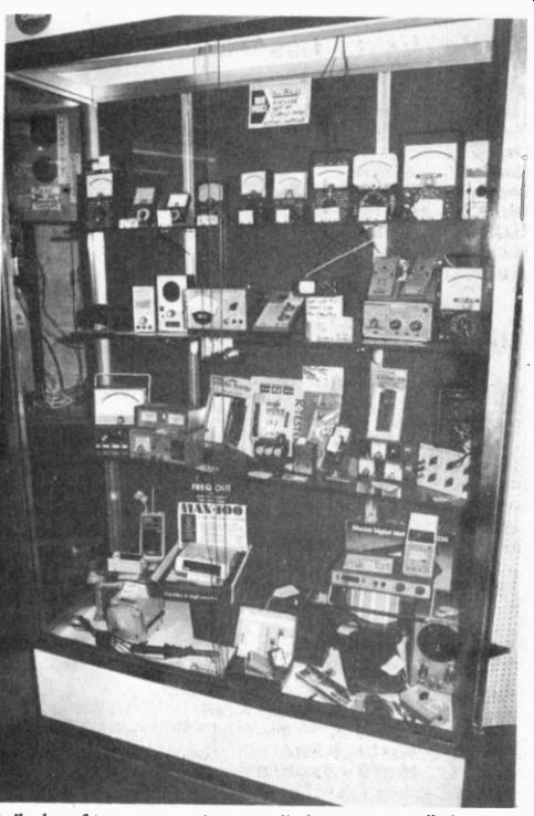
-----------A display of test gear such as you find at many retail shops.
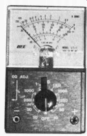
------------A small analog multimeter. This sort of device should sell
low cost.
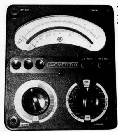
---------- The Avometer is the Rolls Royce of electronic multimeters.
The model 8, pictured left, carries a price tag of over £100 (1979, UK).
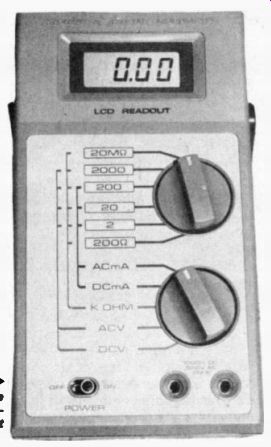
------------The digital multimeter on the right uses a rigid crystal
display (LCD).
ELECTRONIC MULTI METERS are souped up versions of the analog type: They have a built-in electronic amplifier to improve the basic instrument sensitivity and give improved (sometimes) overload protection, but use the same type of moving-pointer readout indicator as the normal analog multimeter.
DIGITAL MULTI METERS are 'all electronic' instruments: they use sophisticated electronic circuitry to convert the magnitude of the parameter under test into a numeric value which is displayed directly on a digital readout unit. These instruments have very good sensitivity. They also have a high degree of overload protection; you can, for example, set them to their 100mV range and then connect them straight across a 500 volt power line without doing any serious damage, which is why we at HE use them!
WHAT TO BUY?
If you are just starting in electronics and expect to stay interested in the subject for some time, you are bound to need at least one multimeter.
Start by buying a reasonable quality analog instrument with a sensitivity of at least 20k /volt and with some kind of overload protection. At a later date you may find it worth while to build or buy an electronic or digital multimeter.
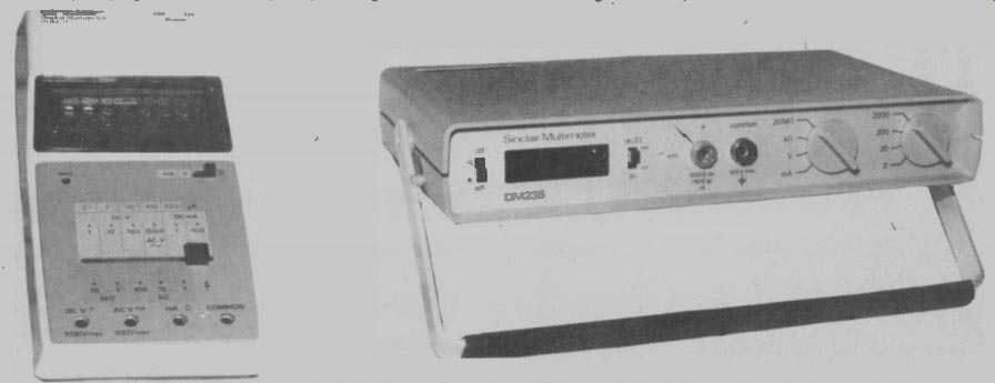
-------- A brace of digital multimeters from Sinclair. Both have
light emitting diode (LED) displays. The PDM 35 (left) sells at about
£30, the DM235 (right) at about £50.
WAVEFORM GENERATORS
Most electronic circuits are concerned with processing waveforms in one way or another: Hi-Fi circuits are concerned with amplifying waveforms with a minimum of distortion: filters are concerned with imparting a kind of frequency distortion to incoming signals: A waveform generator of some kind is thus needed when testing most types of electronic circuit.
Waveform generators are usually classified either by the type of waveform they generate (sine, square, triangle, pulse, etc.), by the area off frequency coverage of the generator (AF, LF, RF, VHF, etc.), or by the technique used in generating the waveform (R-C or L-C oscillator, or function generator, etc.). The better known types of waveform generator are as follows.
AF or LF SINE or SINE/SQUARE GENERATORS produce waveforms from below 20 Hz up to at least 20 kHz (AF types) or 100 kHz (LF types). The basic sine wave is usually produced from an oscillator that uses an R-C (Twin-T or Wien) tuning network and the resulting waveform is usually reasonably pure and typically has a harmonic distortion content of less than 0.5% at the normal test frequency of 1 kHz.
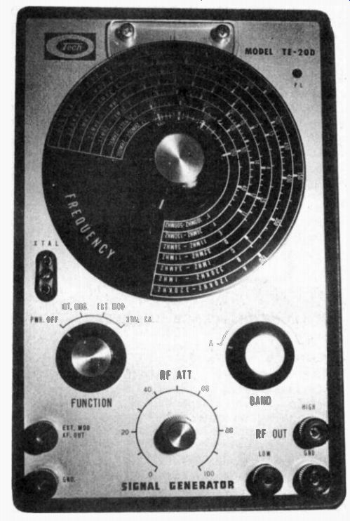
----------- This signal generator will produce frequencies in the
range 120kHz to 500 MHz for a price of around £60.
These generators invariably incorporate some kind of amplitude stabilization circuitry, so that the mean output amplitude of the signal is constant at all frequency settings: In spite of this amplitude stabilization circuitry, most R-C generators suffer from a phenomenon known as 'bounce', in which the amplitude varies in an unstable manner as the frequency control is altered, but then settles down as frequency stability is obtained.
It is a simple matter to convert a sine wave into a square wave, so many AF and LF generators have a facility for generating either a sine or a square waveform, either simultaneously via individual outlets, or alternatively via a mode selector switch.
A good quality sine /square generator is an essential piece of equipment to anyone interested in designing or experimenting with AF or LF amplifiers or filters, and the keen reader is advised to build or buy one at the earliest opportunity.
FUNCTION GENERATORS usually produce a basic triangle wave, which is then modified into a sine form by special circuitry: They also produce a square wave.
Often, these waveforms can be subjected to amplitude and/or frequency-modulation, either via external control terminals or via a built-in auxiliary generator. A major attraction of most function generators is that they cover a very wide frequency spectrum, typically from less than 0.1 Hz to above 100 kHz. A second attraction is that they do not suffer from amplitude 'bounce' as their operating frequency is altered. The only real disadvantage of most function generators is that their sine wave outputs have perceptible distortion (typically between 0.5% and 2%), and they are thus not suitable for distortion testing Hi-Fi amplifiers.
Function generators are nice instruments to own, but are not needed by the average electronics novice: When the novice blooms into an amateur, however, he (or she) may find it worth while building one of these instruments.
PULSE GENERATORS produce waveforms suitable for testing digital electronic circuits. They are usually provided with two built-in variable pulse generator networks (one giving a delay pulse and the other an output pulse) which can be triggered either via an external signal or via a built-in variable-frequency square-wave generator.
A pulse generator is not needed by the average novice, but is an essential item to any keen amateur interested in designing or experimenting with digital circuitry: Pulse generators make good do-it-yourself projects.
RF and VHF GENERATORS produce high-frequency basic (but often highly distorted) sine waves for testing radios, TV's, etc: The generated waveform can usually be subjected to amplitude and/or frequency modulation, either via external signals or via a built-in modulation generator.
These generators are essential items to anyone interested in servicing, repairing, or designing radios or TV's: if you need one, buy it rather than build it: DIY versions are difficult to construct, and very difficult to calibrate.
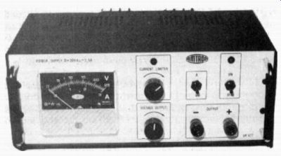
---------- The power supply above is available in kit form (see last
month's issue) and costs about £40.
VARIABLE POWER SUPPLIES
Variable power supplies enable you to power an experimental circuit via the mains, rather than from batteries, and usually give a regulated output that is variable from zero up to at least 20 volts, at currents up to at least 1 amp: All good designs have some form of overload protection, so that the instrument does not disintegrate when you place that accidental short across its output.
Some designs of variable power supply provide only a single output (e.g., 0-20 V): Others provide either a split output (e.g., 0 to t 20 V), or have two independent outputs (e.g., 2 X 0-20 V). The split-output type of power supply is ideal for powering experimental op-amp (operational amplifier) circuits.
A decent variable power supply is an essential item to any amateur interested in experimenting with electronic circuitry. DIY power supplies are easy projects to build.
OSCILLOSCOPES AND ACCESSORIES
An oscilloscope is an instrument that lets you look at an actual waveform appearing in any part of a circuit. The instrument has a small TV-type of screen which has its face covered with a graduated scale or graticule which is marking in both the horizontal and vertical axis. The instrument also has a number of front panel controls which are calibrated in relation to the graticule scales.
Thus, it is possible to display an unknown waveform on the 'scope and know, merely by looking at its shape and its relationship to the graticule and control settings, that it is (for example) a 15 kHz distorted sine wave with a peak-to-peak amplitude of 2.7 volts.
An oscilloscope is probably the most useful (but most expensive) instrument in any electronics workshop or laboratory. 'Scopes come in a variety of types, and can be used with a variety of accessories. The most import ant ones are as follows:
'BASIC (SINGLE TRACE) OSCILLOSCOPES have a 'Y amplifier', which has its controls graduated in relationship to the vertical scale of the tube graticule, and an 'X amplifier' or timebase, which has its controls graduated in relationship to the horizontal scale of the graticule. Modern 'scopes use a triggered timebase, which provides the X axis with meaningful calibration: Older 'scopes have a free-running timebase, which gives almost meaningless calibration to the X axis.
One of the most important parameters of a 'scope is its bandwidth, or frequency-display capability. Old fashioned 'scopes could handle AC-coupled inputs only and had typical bandwidths extending from 20 Hz up to about 1 MHz. Modern 'scopes are DC coupled and have bandwidths that extend down to zero at the low end and up to about 5 MHz on low-priced 'scopes, or 15-25 MHz on medium priced 'scopes, or 100-225 MHz on high priced 'scopes.
DUAL TRACE OSCILLOSCOPES are capable of displaying two waveforms at the same time. This is useful, for example, if you want to look simultaneously at the input and the output waveforms of a circuit. These 'scopes have two calibrated and independent Y amplifiers, which provide the display drive. The final display is either obtained from a special dual beam tube, or more commonly, from a single-beam tube that has its beam electronically chopped to provide the illusion of two independent beams.
OSCILLOSCOPE TRACE DOUBLERS are add-on devices or accessories that can be used to give a single-trace 'scope a dual-trace capability.
DUAL SWEEP (DUAL TIMEBASE) OSCILLOSCOPES are provided with two time-bases, which can be used independently, alternately, or with one triggering the other. These 'scopes can let you do fancy things, such as look at a one microsecond wide pulse superimposed on a 1 kHz square wave and occurring 470uS after the leading edge of the square wave. (Not many amateurs need this facility.) OSCILLOSCOPE CALIBRATORS are fairly simple accessories that enable the owner to measure and adjust the calibration accuracy of the Y and/or X axis of an oscilloscope.
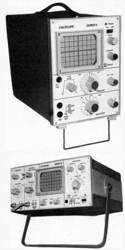
Top: A single beam oscilloscope like this will cost around £150.
Above: A dual beam oscilloscope with a price tag of £340.
WHAT TO BUY?
A 'scope is the most useful instrument in any electronics workshop or laboratory, so if you can get one, do so. A single-beam single-timebase instrument is adequate for most amateur uses. Ideally, the Y amplifier should have DC-coupling, with an upper bandwidth limit of at least 3 MHz, and the timebase should be the triggered type: On the other hand, any 'scope is better than none at all, and good 'scopes tend to be rather expensive.
MISCELLANEOUS TEST GEAR C-R and LCR BRIDGES are specialized instruments that let you measure the precise values of resistors (R), capacitors (C), or inductors (L). They are nice instruments to own, but are only rarely used or needed by the novice. They are, nevertheless, fairly easy and interesting projects to build.
ANALOG FREQUENCY METERS look similar to a normal multimeter, but are designed only to measure frequency. Typical frequency coverage is 100 Hz to 1 MHz full scale, and typical accuracy is 2% or 3% of full scale. Sometimes these instruments are designed as DIY add-on units for use in conjunction with a normal multimeter, and are well worth building in this form.
DIGITAL FREQUENCY METERS give a direct read out of frequency from a few Hz up to tens or hundreds of MHz, with a typical accuracy of .001 % or better. They are very useful instruments for the serious experimenter or designer, but are fairly expensive to buy or build.
DISTORTION FACTOR METERS are specialized instruments for rapidly measuring the distortion content of audio-frequency waveforms. They are only essential instruments for the serious Hi-Fi designer and experimenter, but are fairly easy projects to build.
ANALOG VOLT/MILLIVOLT METERS are multirange electronic instruments with typical full-scale range coverage extending from 1 mV to 1000 V AC and/or DC. They are particularly useful for measuring low-level signals in audio amplifiers, etc., and are popular DIY projects.
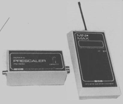
Top: An LED frequency counter for about £60, and a prescaler (which
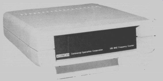
divides the input frequency by 10) for about £40. Above: A wider
ranging frequency counter; this one goes for about £80. (1979 UK prices)
STARTING A WORKSHOP
If you are going to take electronics seriously, you're going to need some test gear. So what do you need? Our advice is to take the following four steps, and then progress from there:
1. The first instrument you will have to get, and one that you will always need, is a decent multimeter. Buy, rather than build one, and make sure it has a sensitivity of at least 20 k / volt, and has some kind of overload protection.
2. The next item to acquire is a waveform generator. If your field of interest is audio or LF, build yourself a decent sine/square generator. If you're a radio or TV buff, buy yourself an RF or VHF generator. If you only like digital circuits, build a pulse generator.
3. Build or buy a decent variable power supply. This is an essential item to anyone interested in designing or experimenting with electronic circuits.
4. Whatever your field of interest, try at some time to acquire an oscilloscope of some kind, no matter how tatty it is: These instruments add a whole new dimension to the field of hobby electronics.
-------Our thanks to Audio Electronics of Edgware Road, London for allowing us to use their showroom and stock as photographic studio and models for this article.
(adapted from: Hobby Electronics magazine, Mar. 1979)
Also see: Into Electronics--Part 5: Oscillators