This feature was prepared from '50 FET Projects' by F. G. Rayer, published by Bernard Babani at (mult by 1.4 for dollar) £ 1.25. It contains many practical constructional projects using readily available FET devices.
As our project editor is always saying, the best way to get to know something is to get it on the work bench in front of you. This month we get hold of the FET and show you just what you can do with it (no that's not meant to be rude).
INTRODUCTION
FIELD EFFECT TRANSISTORS find application in a wide variety of circuits. The projects described here include radio frequency amplifiers and converters, test equipment and receivers, as well as various miscellaneous devices which are useful in the home.
It will be found that in general the actual FET used is not critical, and many suitable types will perform satisfactorily. The FET is a low noise, high gain device with many uses, and the dual gate FET is of particular utility for mixer and other applications.
This article should be found to contain something of particular interest for every class of enthusiast--short wave listener, radio amateur, experimenter, or audio devotee.
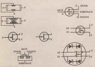
Fig. 1. Construction and symbols used for field effect transistors.
FET OPERATION
Figure 1 will help clarify the working of the field effect transistor. (a) represents the essential elements of the device, which has Source lead S, Gate lead G, and Drain connection D. The path for current is from Source to Drain through the semi-conductor material, this path being termed the channel. With the N-channel FET, the carriers are electrons. The Source is connected to negative of the supply, and Drain to positive.
P-type gates are formed on the N-type channel, providing PN junctions. When these junctions receive reverse bias, areas surrounding them are emptied of electron carriers. These "depletion areas"' reduce the width of the carrier channel, as at (b). As a result there is a drop in the passage of current carriers from Source to Drain. Increasing the bias causes the depleted regions to extend, and the channel grows smaller, reducing current even further. Eventually the gate can be made so negative ,that the channel is virtually closed. This is the pinch off region, and current is practically zero. The current from source to drain, and through external circuit items, can therefore be controlled by adjusting the gate voltage. Since the gate to channel junction area is reverse biased gate current is extremely small, and thus the gate input impedance is very high. Generally, the gate current is negligible.
(c) is the symbol for this FET, with S indicating Source (negative), G for Gate, and D for Drain (positive).
Such N-channel FETs are conveniently operated with a negative ground or source line. "D" is the symbol for a P-channel FET. Typical types and lead outs are shown later.
(e) represents an insulated gate FET. The gate is insulated from the channel by an extremely thin dielectric so that there is no junction in the way described for '(a). The substrate is P-type material with positive hole carriers. When the gate is made negative, positive charges move from the substrate towards the gate, so that the width of the conducting channel is reduced, and thus also the current from drain to source.
MEDIUM FREQUENCY AMPLIFIER
This circuit, Figure 2, is primarily intended for use over the 1.7MHz to 30MHz range, and will be found to provide considerable gain. RF amplifiers of this kind are generally used to improve long distance short wave reception, to increase volume, and to reduce second channel interference on the higher frequencies.
To avoid winding coils and permit easy band changing, Denco ( Clacton) miniature plug in coils may be used. These are the "Blue" (Aerial) ranges, valve type. The most useful coils will be Range 3, 1.67 5.3MHz, or 580 to 194 meters; Range 4, 5-1 5MHz, or 60 to 20 meters; and Range 5, 10.5-31.5MHz, or 28 to 9.5 meters. Exact coverage depends on the setting of the adjustable cores, and will also be modified if VC1 is of different value. The coils are inserted in a B9A type holder. If only a single range is wanted, the coil can be mounted by its threaded end, and leads are then soldered directly to the pins.
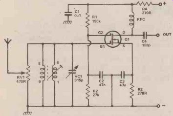
Fig. 2. Circuit diagram for a Medium Frequency RF amplifier.
RV1 is an adjustable aerial input control, as over loading may easily arise with strong signals. R1 and R2 provide the voltage for gate 2, and R3 is for source bias.
The drain circuit is arranged for capacitor coupling by C4 to the aerial socket of the receiver. This lead should not be unnecessarily long, as this may cause losses, as well as picking up signals which cause second channel interference. If the lead is screened, it must be no longer than necessary. A 2.6mH short wave sectionalized radio frequency choke will be satisfactory for the frequencies mentioned.
Construction is best in a metal case, which can have a hinged lid if plug-in coils are to be fitted. No ganging difficulties can arise with VC1, which is adjusted for best volume.
Second channel interference is caused by signals which are 2 x 1F frequency from the wanted signals.
With a 470kHz intermediate frequency, these offending signals will be 940kHz from the wanted transmission.
As a result, interference from this cause is unlikely at low frequencies, but very probable at high frequencies. Such second channel interference is considerably reduced, or completely avoided, by using a tuned RF stage of this kind, actual results in this direction depending on the receiver IF, and frequencies tuned.
A 9 V supply is adequate, and current may be drawn from the receiver if convenient. Only about 2mA to 3mA or will be wanted. The MEM618, 40602, and 40673 will be found satisfactory here.
144 MHz CONVERTER
The reception of 2 meter signals is generally with a converter and short wave receiver, preferably of communications type. The latter will have sensitivity and selectivity better than average. With such an arrangement of equipment, the 144MHz or other VHF signal is changed in frequency so that the converter output falls within the tuning range of the receiver.
A converter of this type often has its own RF amplifier, and a relatively low frequency crystal controlled oscillator, followed by frequency multipliers. This allows high sensitivity and excellent frequency stability, but is a relatively complicated and expensive item. Bearing in mind that at this frequency the RF amplifier will not contribute very much gain, and that tunable VHF oscillators are used in many domestic VHF receivers, it is possible to use the much simpler circuit in Figure 3.
L1 is broadly tuned to the wanted frequency band by T1, and signal input is to gate 1-of Q1, Q2 is the local oscillator, and the operating frequency here is deter mined by L2 and T2. Oscillator injection is via C3 to gate 2 of Q1. The frequency of the output from the drain of the mixer Q1 is the difference between G1 and G2 frequencies. Thus if the signal at G1 is 144MHz, and Q2 is tuned to oscillate at 116MHz, output will be at 144 minus 116MHz, or 28MHz. Similarly, with the oscillator set at 116MHz, an input at 146MHz to G1 will give an output of 30MHz. Therefore 144-146MHz can be covered by tuning the receiver from 28MHz to 30MHz.
L3 is broadly tuned to this band, and L4 couples the signal to the short wave receiver.
The oscillator can actually be tuned above or below the aerial circuit frequency of the converter, as it is the difference between converter signal input and oscillator frequencies which determines the converter output frequency. It is also possible to choose other reception and output frequencies, provided L1 , L2 and L3 are chosen to suit.
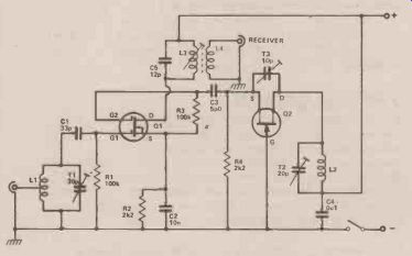
Fig. 3. Circuit for a 144 MHz converter for short wave receivers.
L1 and L2 are wound in the same way, except that L1 is tapped one turn from its grounded end. Each coil has five turns of 18 swg wire, self supporting, formed by winding the turns on an object 7mm in diameter. Space turns so that each coil is ½-in or about 12mm long.
L3 is fifteen turns of 26 swg enameled wire, side by side on a 7mm former with adjustable core. L4 is four turns, overwound on the earthed (positive line) end of L3. Layout should allow very short connections in the VHF circuits. A co-axial aerial socket is fitted near L1. A screened co-axial lead is preferred from L4 to the receiver, to avoid unnecessary pick-up of signals in the 28-30MHz range. The converter will operate from a 9 V to 12 V supply.
L3 should first be peaked at about 29MHz. If a signal generator is available couple this to Q1 drain by placing the output lead near the drain circuit. Tune generator and receiver to 29MHz, and adjust the core of L3 for best results. Otherwise, couple an aerial by means of a small capacitor to the drain circuit, and tune in some signal in the 28-30MHz range, to allow adjustment of the core of L3.
It is now necessary to tune L1 to about 145MHz, and L2 to 116MHz, or 1 74MHz. If an absorption frequency indicator is available, this will permit an approximate setting of T2. A dip oscillator will also allow T1 to be adjusted. Subsequently adjust T2 to bring the wanted signals in at the required frequencies on the receiver, and peak these for best volume with T1, and check the setting of L3 core.
The converter is best assembled in a small aluminum box, completely closed, which can be placed behind the receiver. Note that if Q2 is not oscillating, no reception is possible through the converter. Q2 should be a VHF FET, such as the 1244, MPF102, and similar types, and if Necessary T3 may be adjusted to secure oscillation here. The 40602, 40673, and similar VHF types will be satisfactory for Q1. If needed, frequencies can be brought within the swing of T1 and T2 by stretching or compressing L1 or L2.
The aerial may be about 381/2in long, constructed as a simple self-supporting or wire dipole, with a feeder descending to the converter. Amateur activity is most likely to be greatest at weekends, and in many areas a whip or very short wire aerial will provide local reception.
FIELD STRENGTH METER
The device in Figure 8 will operate at any frequency up to 250MHz or even higher if necessary. A short whip, rod, telescopic or other aerial picks up radio frequency energy, and rectification by diode D1 provides a positive voltage for the FET gate, across R1. This FET is only operating as a DC amplifier, and the 2N381 9 and other general purpose transistors will be satisfactory.
The "Set Zero" potentiometer may be 1k to 10k.
With no RF signal present, it allows gate/source potential to be adjusted, so that the meter shows only a small current, which rises in accordance with the strength of the RF present. For high sensitivity, a 100 uA meter can ...
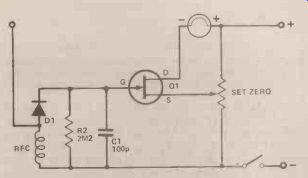
Fig. 4. Field strength meter, useful for determining the efficiency
of RF equipment.
... be fitted. Alternatively, a meter of lower sensitivity, such as 25 uA, 500 uA or 1 mA can be used, and will provide enough indication in most circumstances.
Should the field strength meter be wanted for VHF only, a VHF choke can be used, but for general usage over lower frequencies, a short wave choke is necessary.
An inductance of about 2.5mH is satisfactory for 1.8MHz and higher frequencies.
The device can he constructed in a small insulated or metal box, with the aerial projecting vertically. In use, it allows tuning up a transmitter final amplifier and aerial circuits, or the adjustment of bias, drive and other factors, to secure maximum radiated output. The effect of adjustments will be shown by the rise' or fall of the reading of the field strength meter.
FET TRF RECEIVER
Figure 9 is a circuit giving good headphone reception for persons listening, and it can if wished be constructed as a miniature receiver with a short throw-out aerial. Alternatively, it can be used with reduced range by relying on the ferrite rod alone for signal pick-up.
Q1 is the detector, and regeneration is obtained by tapping the source up the tuning coil. The use of regeneration greatly improves selectivity, and also sensitivity to weak signals. The potentiometer RV1 allows manual adjustment of the drain potential of Q1, and so-acts as a regeneration control.
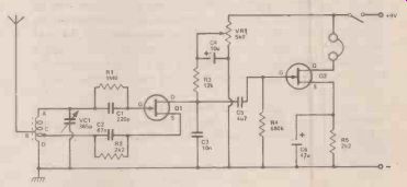
Fig. 5. FET TRF receiver.
Audio output from Q1 is coupled to Q2 by C5. This FET is an audio amplifier, operating the headphones. A complete headset is preferable for general listening, and phones of about 500 ohms DC resistance, or about 2k impedance, will give very good results here. If a miniature earpiece is wanted, this should be a medium or high impedance magnetic unit. A crystal earpiece will require resistance capacity coupling.
The tuning inductor is fifty turns of 26 swg wire, on a ferrite rod about 5 in. x 3/8in. If the turns are wound on a thin card sleeve which can be moved on the rod, this will allow adjustment of band coverage. The winding begins at A, and aerial tapping B is at about twenty-five turns. D is the grounded end of the coil. The best position of the tapping C depends somewhat on the actual FET, on the battery voltage, and on whether the receiver is to be used with an external aerial wire or not.
Should the tapping C be too near to end D, no regeneration will be obtained, or regeneration will be weak, even with RV1 rotated for maximum voltage. On the other hand, with too many turns between C and D, oscillation will begin with RV1 only slightly advanced, and signals will be weak. Best results are expected when regeneration begins smoothly, with RV1 about halfway through its rotation. It was found that only one to two turns were required between C and D. As changing the whole coil by a turn or so has little practical effect on frequency coverage, the best method is to make C two turns from D. Then if necessary unwind half a turn or more at D.
When regeneration is obtained, a heterodyne will be heard if the receiver is tuned through a transmission.
RV1 should then be turned back very slightly. Maximum possible sensitivity is achieved when Q1 is almost in the oscillating condition. RV1 has to be set to suit the frequency tuned by VC1, so that final critical adjustment can be made. It is useless to regard RV1 as a gain control, and set it at maximum.
A metal case is suitable where an external aerial wire will be used. Where the ferrite rod only will be employed, for local signals, the box or case must be of plastic or other insulating material.
TIMER
An adjustable timer, giving a delay of about 10 seconds to 1 minute, can be used for photographic and other purposes; or with various games where each competitor must make his move within the agreed period.
The circuit in Figure 11 can be employed in various ways, as will be explained. When the switch is moved to the "On" position timing begins, and C1 commences to charge through R1 and RV1. The two resistors R4 and R5 hold the source of Q1 at approximately a fixed potential. When the voltage across C1 has reached a high enough level Q1 gate is positive, so that drain current flows through R3. This causes a voltage drop in R3, so that the base of Q2 moves negative. Q2 is a PN P transistor, so conducts, and collector current flows in the relay coil, closing the relay contacts. When the switch is returned to the "Off-position, C1 is discharged through R2, so that the interval can be repeated.
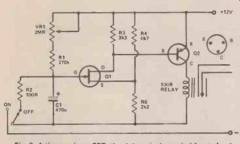
Fig. 6. A timer using a FET, the delay can be varied from about 10 seconds
to 1 minute.
A 2N3819 is suggested for Q1, and AC128 for Q2.
With C1 as shown (470uF) the interval was found to lie between 10 seconds with a total of 250k in the R1 / RV1 position, up to 1 minute with 2 megohm. So the values in Figure 42 can be expected to allow any interval to be set from approximately 10 seconds to 60 seconds.
Increasing C1, R1 or RV1 will lengthen the interval.
Smaller values here will reduce it. This was with current rising to 40mA, with a 100 ohm relay.
It is not of course essential that these values or transistor types be followed exactly, and other relays would also be practicable, provided the circuit and Q2 allows a satisfactory current and voltage to suit the winding. Generally, a relay with a coil resistance of about 100 to 250 ohms will be most satisfactory.
The relay contacts can be so wired, that when the relay coil is energized, the circuit is completed, or interrupted. The former will most usually be wanted.
Closure of the contacts can then light an indicator lamp, or sound a buzzer or bell. The use of opening contacts will be convenient for repeating a set interval when enlarging. A 2-pole 2-way switch is then required, so that switching the timer on lights the lamp to begin the exposure, which continues until the relay contacts open.
For games and similar purposes, a 12 volt 3 watt indicator lamp can be operated from the same 12 V supply. Should any kind of mains-voltage circuit be controlled, the relay must be a type intended for this purpose, and care must be taken to arrange mains circuit so that no danger can arise for the user.
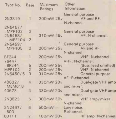
-Table showing all the important parameters for the various
FETs used in the circuits, the types used are all freely available and
with only one or two exceptions are not very specialized.
This article is reproduced by kind permission of Bernard Babani (Publishing) Ltd, The Grampians, Shepherds Bush Road, London W6 7N F, and taken from the book 50 (FET) Field Effect Transistor Projects by F. G. Rayer. The book (Bernard Babani No. BP 39) is available from most component shops price (mult by 1.4 for dollar) £ 1.25. It is also available from the HE Book Service, see ad in this issue.
---------
(adapted from: Hobby Electronics magazine, Sept. 1979)
Also see:
Thyristors: The Great Gate Story
Electronic Timekeeping---Seconds Out