AMAZON multi-meters discounts AMAZON oscilloscope discounts
Table of Contents:
- Introduction
- Resistance in Series Circuits
- Review
- Self-Test Questions
- Current in Series Circuits
- A Simple Series Circuit
- Multiple Resistor Circuits
- Review Self-Test Questions
- Voltages in Series Circuits
- Voltage Drop
- Kirchhoff's Law
- Review Self-Test Questions
- Power in Electrical Circuits
- The Watt
- The Kilowatt Hour
- Review
- Self-Test Questions
- Answers to Self-Test Questions
- Lesson Questions
--------------
Lesson Objectives
In this lesson you will ...
• Use Ohms law to find current and voltage in series circuits.
• Apply Ohm's law in different forms to determine the relationship between current, voltage, and resistance in a series circuit.
• Learn how Kirchhoff 's law establishes the voltage drops in a series circuit.
• Learn the basic units of electrical power and how electrical power relates to current, voltage, and resistance.
INTRODUCTION
You have studied voltage, current, resistance, and the units of measure for each. You know that current is measured in amperes, milliamperes, and microamperes. You have also learned that volts, millivolts, microvolts, and kilovolts are units of voltage. In addition, you should remember that resistance is measured in ohms, kilohms, and megohms. These should all be familiar terms. You should know what they mean, and know how to make a conversion from one unit to another.
So far, we have shown you simple series circuits. In a series circuit, there is only one path for current to travel. If a resistor is connected between the negative and positive terminals of a battery, electrons must leave the negative terminal of the battery, flow through the resistance to the positive terminal of the battery, and back through the battery to the negative terminal.
There is only one path for current flow.
A series circuit may contain many resistances.
The resistors are connected end-to-end so that electrons flow through each resistor moving from one to the next.
A parallel circuit has multiple paths for current flow. Each resistance may connect directly to the voltage source, or several resistances may branch from a junction. We say that the entire resistive load is "across" the battery in parallel, and there may be many parallel paths for current flow.
Electrons leaving the negative terminal of the power source will flow through several different paths to get to the positive terminal.
You will study series circuits in this lesson, and parallel circuits in the next. All circuits found in electronic equipment are either series circuits, parallel circuits, or combinations of both.
RESISTANCE IN SERIES CIRCUITS
A series circuit has only one current path, as shown in Fig.1. The current is the same in all parts in the circuit. The current flowing through R1 is the same as the current flowing through R2 and R3. We will use examples of circuits made up of resistors. A series circuit may use many different types of electronic components, however. For example, you could have a series circuit containing several resistors, a transistor, and a coil.
Battery voltage and resistor values for the circuit shown in Fig. 1 are provided in Fig.2. In this series circuit, each resistor opposes the flow of current. The total opposition to current flow is equal to the sum of the resistances of the individual resistors. We can express this mathematically as:
RT = R1 + R2 + R3
Therefore, in Fig.2, the total resistance is:
RT = 3 + 7 + 5 = 15 ohms
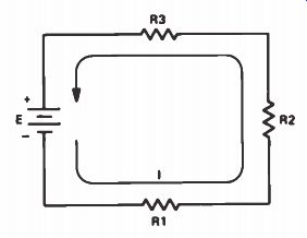
Figure 1. A series circuit.
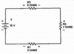
Figure 2. A series circuit.
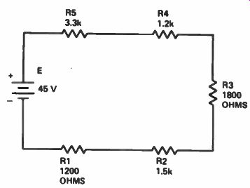
Figure 3. A series circuit with five resistors.
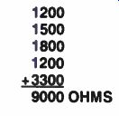
Figure 4. Total value of the resistors in Flg.3.
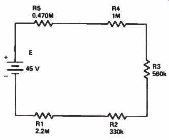
Figure 5. A series circuit with five resistors.
The three resistors together have a total resistance of 15 ohms. That is, in this series circuit, the same current would flow if the three resistors were replaced with one 15-ohm resistor.
Polarity. In Fig.2, electrical current leaves the negative terminal of the battery and flows through R1, R2, and R3. The flow of current through each resistor creates a voltage polarity across it. The polarity of voltage across R1, for example, makes the end connected to the battery more negative than the end connected to R2. The same applies to the junction of R2 and R1; it is more negative than the junction of R2 and R3.
The concept of polarity applies to any component through which current flows. If you were measuring the voltage at different points in the circuit, your knowledge of polarity would enable you to properly connect a meter to the circuit, with the positive meter lead connected to a point more positive than the connection of the negative lead. Polarity is frequently marked on diagrams with small + and - signs. We will discuss this in greater detail later.
Calculating Series Resistance. A more complex series circuit is, which has five resistors instead of three, shown in Fig.3. Some resistance values in the circuit are provided in ohms, others in kilohms (k). To find the total resistance in the circuit, we must convert all resistor values to the same unit.
Let's convert the values to ohms. R1 is already given in ohms--as 1200 ohms. R2 is 1.5 kilohms.
To convert this to ohms, simply multiply by 1000, moving the decimal points three places to the right, so that 1.5k equals 1500 ohms. R3 is given in ohms, as 1800 ohms. R4 is 1.2k, which equals 1200 ohms. Similarly, R5 is 3.3k, which is equal to 3300 ohms. As shown in Fig.4, the total resistance is the sum of all five resistance values, or 9000 ohms.
Another circuit containing five resistors is shown in Fig.5. Some of the resistor values are given in megohms (M), others in kilohms. Before you can add the values together to get the total resistance, you must convert all the resistances to the same unit. You can convert all the values to ohms, kilohms, or megohms. It doesn't matter which unit you convert to, as long as they are all the same.
To convert megohms to kilohms, move the decimal point three places to the right. To convert megohms to ohms, move the decimal point six places to the right. To convert kilohms to ohms, move the decimal point three places to the right. To convert kilohms to megohms, move the decimal point three places to the left.
The five resistors we have examined are shown converted to the same unit in Fig.6, on the next page. In the first column, all resistance values have been converted to ohms. In the second column, all have been converted to kilohms, and in the third column, all have been converted to megohms.
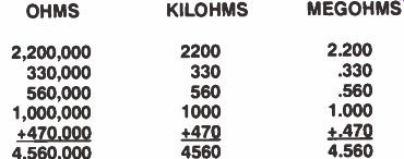
Figure 6. The resistances in Fig.5 converted to the same units.
You can see from Fig.6 that we get the correct answer in each case. You can see that 4,560,000 ohms is equal to 4560k, and to 4.560 megohms.
For practical purposes of calculation, you can ignore low-value resistors in a series circuit if one or more resistors has a much higher value than the others. In this case, the low resistances will not appreciably change the total circuit resistance.
In Fig.7, for example, resistors R1, R2, R4, and R5 have very small resistances compared to R3. With only R3 in the circuit, its 4.7M produces a current of 9.57 microamperes. If we add the other resistor values, the total becomes 4,704,700 ohms. Using that value as the total resistance, the current is 9.56 microamperes.
The difference is 0.01 uA, which is insignificant.
Thus, for practical purposes, we could say that the circuit resistance is effectively 4.7 megohms.
Does this mean that we can ignore the presence of the other components? No. We point this out because it is important to remember that current flow in a series circuit with one or more high-value resistors and one or more low resistance resistors is determined primarily by the high-value resistors. However, the low-value resistances probably have very specific purposes. Because of their small values, the low value resistors could be shorted out of the circuit, and not significantly affect the total current. But the loss of their special function in the circuit might drastically affect its overall performance.
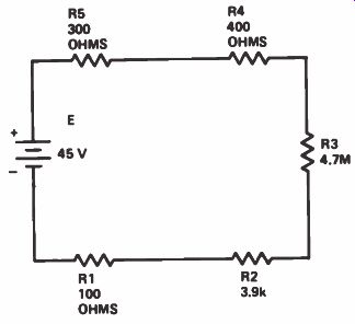
Figure 7. A series circuit where R1, R2, R4, and R5 can be ignored when
determining the total resistance.
Review
A series circuit is a circuit in which there is only one path through which the electrons can flow. The electrons leave the negative terminal of the voltage source and flow through one part after the other, and back to the positive terminal.
The current is the same in all parts of a series circuit. The direction of current flow establishes a voltage polarity across each component.
Self-Test Questions
1. What is a series circuit?
2. If R1 equals 3 ohms, R2 equals 4 ohms, and R3 equals 5 ohms, what is the total resistance of the three resistors in series?
3. If these five resistors are connected in series: R1 equals 1500 ohms, R2 equals 2.2k, R3 equals 2700 ohms, R4 equals 4.7k, and R5 equals 1000 ohms, what is the total resistance?
4. If these five resistors are connected in series: R1 equals 3.3M, R2 equals 680k, R3 equals 560k, R4 equals 2.2M, and R5 equals 470,000 ohms, what is the total resistance?
CURRENT IN SERIES CIRCUITS
As a technician maintaining electronic equipment, you will seldom have to calculate the current flow in the circuit. However, occasionally you will want to know what the current should be. Calculating the current flow in a circuit is very simple - you use Ohm's law in the form:
E I = - à -
where I = current, E = voltage, and R = resistance.
A Simple Series Circuit
Figure 8 is a schematic of the simplest series circuit you will encounter. It is made up of a 12 V voltage source and a single resistor. Suppose R1 has a resistance of 6 ohms, and we want to find the current flow in the circuit. To do this, we substitute 12 for E and 6 for R in the Ohm's law formula and we have:
12 I = = 2 A 6
You will seldom find resistances as low as 6 ohms in electronic equipment. Most often the resistance will be in kilohms or megohms. You use the same form of Ohm's law to find the current flow, but you must first convert the resistance to ohms.
As an example, suppose R1 in Fig.8 has a resistance of 1.2 kilohms. To find the current flow, we first convert 1.2k to 1200 ohms. Then we substitute for E and R in the formula, and we have:
12 I - 1200
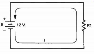
Figure 8. A simple series circuit.
If you have a pocket calculator, you can enter the numbers and perform the division. Your answer will be 0.01 ampere. Rather than work with a decimal number, we simply move the decimal point three places to the right and say that the current is 10 milliamperes (mA). If you don't have a pocket calculator, and don't like working with decimals, you can multiply by 1000 and you'll get the current in milliamperes.
For example:
12 1000 I - x 1200 1
Next, simply cancel out two of the 0s above the division line and the two 0s below the division line:
, 12 10 I=i x 2 1
Finally, divide 12 into 12 and multiply by 10: 1 = - 12 X 10 = 1 X 10 = 10 mA 12
Now let's suppose the resistance of R1 in Fig.8 is 600 kilohms. First, you convert this to 600,000 ohms. If you have a calculator, you can enter the values for E and R. Your answer will be either 0.00002 or 2 x 10⁻⁵, depending on the type of calculator you have. This is the current in amperes. You can move the decimal point six places to the right to convert 0.00002 A to 20 microamperes (µA). If you do not have a calculator, you can still find the current. Simply enter the values for E and R in the formula and you have: 12 600,000 If you multiply by 1000 to get the answer in milliamperes, you will still have the problem of dividing 600 into 12. You can get around this by multiplying by 1,000,000. Your answer will be in microamperes:
= 12 x 1,000,000 I 600,000
This looks complex, but allows you to simply cancel five 0s above and below the division line:
12 x 1,000,000 I - 600,000
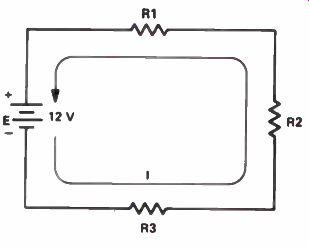
Figure 9. A series circuit with three resistors.
Cancelling the five 0s leaves you with: 12 x 10 I= 6
Finally, you divide 6 into 12 to get 2, then multiply by 10, or you can multiply 12 by 10 to get 120, and divide by 6 to get the current, 20 microamperes.
Multiple Resistor Circuits
The same form of Ohm's law can determine the current flow in a series circuit containing two or more resistors. However, you must first add up the total resistance in the circuit. For ex ample, if in Fig.9, R1 equals 1.2k, R2 equals 1.8k, and R3 equals 1000 ohms, you first convert the values of R1 and R2 to ohms, and then add the three resistance values. The total resistance in the circuit is 4000 ohms. This value fits into the formula:
12 I. 4000
To get milliamps: 12 x 1000 I - 4000
Cancel 0s above and below the line:
12,000 4000 12
= 4
= 3 mA
The total current flow in the circuit is 3 milli amperes. The battery supplies 3 mA; the current through R3 is 3 mA; the current through R2 is 3 mA; and the current through R1 is 3 milliamperes. It is a series circuit, and the current in all parts of the circuit is the same.
You use the same procedure for a series circuit, regardless of the number of resistors in the circuit. First, you find the total resistance in the circuit by converting all resistances to ohms and adding them. Use the total resistance in the circuit, along with the source voltage, to calculate the current flow in the circuit.
Review
In this section we have demonstrated how to find the current in a series circuit. In each case, we use Ohm's law in the form:
I =
To find the current flow in a series circuit, first find the total resistance in the circuit. The voltage must be expressed in volts and the resistance in ohms, To avoid a decimal division, you can multiply by 1000 to get the current in milliamperes. If necessary, you can multiply by 1,000,000 to get the current in microamperes.
Self-Test Questions
5. What is the current in a series circuit made up of three 4-ohm resistors if the applied voltage is 24 volts?
6. A 3k, a 1000-ohm, and a 2k resistor are connected in series across a 12 V battery. What is the current?
7. Four resistors are connected in series across a 120 V battery
If R1 equals 2.2M, R2 equals 600k, R3 equals 1.2M, and R4 equals 2,000,000 ohms, what is the circuit current?
VOLTAGES IN SERIES CIRCUITS
In a series circuit having several resistances, if you know the current flow and the resistance values in the circuit, you can find the voltage across each resistor by using Ohm's law in the form: E=IxR We shorten this formula by leaving out the multiplication sign and writing it as: E = IR
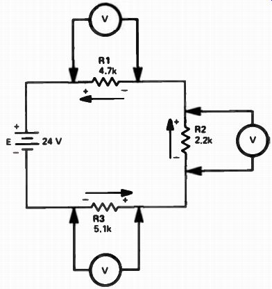
Figure 10. A series circuit showing the polarity of the voltage drop
across each component.
Voltage Drop
Voltage creates, or forces, the flow of electric current through resistances in a series circuit.
Each resistance uses up some of the total voltage in the process. The voltage across the resistance, or across any load, is the amount necessary to force current through it. The voltage across a part in a circuit is called the "voltage drop." The direction of current flow establishes the polarity of the voltage drop.
Look at Fig.10, which shows three resistors connected in series. As illustrated, a voltmeter can be connected across each resistor to measure the voltage, according to the polarity of the voltage that appears across the resistor. Reversing the connections to the voltmeter will result in a reading of negative voltage on the meter.
In the circuit shown, electrons leave the negative terminal of the 24 V battery and flow through R3 in the direction indicated by the arrow. The current flow through R3 produces a voltage across the resistor. The end that the electrons enter is negative, and the end from which they leave is positive. The portion of the 24 V used up across the resistor is the voltage drop.
To determine the voltage drop across R3, we must first determine the circuit current. Adding the resistance of the three resistors to get 12,000 ohms, we divide 24 V by 12,000, and calculate a current of 0.002 ampere. Now, using the resistance in ohms and the current in amperes, we can determine the voltage E3 across R3. We substitute 0.002 for I, and 5100 for R to get: E3 = 0.002 x 5100 = 10.2 V
We can go ahead and calculate the voltage across R2 and the voltage across R1 in the same way. We will find that the voltage across R2 is 4.4 V and the voltage across R1 is 9.4 volts.
Now, add the three voltage drops together and we have:
E = 9.4 + 4.4 + 10.2 = 24 Notice that the sum of the voltage drops is equal to the applied voltage. This is always true in any series circuit. In any closed series circuit, the sum of the voltage drops will be equal to the source voltage.
Kirchhoff's Law-- Kirchhoff's law is an important rule electronics. It states that in any closed series circuit, the sum of the voltage drops will be equal to zero. Let's look again at Fig.10 and see exactly hat this means.
If you beginning -- from the negative terminal of the battery, you first arrive at R3. The voltage polarity across R3 is such that you move from negative to positive as you go through R3. Again, at R2 you move from negative to positive following the current path, and once again from negative to positive through R1.
When you reach the battery, however, you encounter the positive terminal. If you continue moving in the direction of current flow, you travel from positive to negative, not negative to positive as you did with the resistors in the external circuit. The source voltage polarity is opposite from the polarity of the voltage drops in the load resistances.
Reflecting back to Kirchhoff's law, we are looking for the sum of the voltage drops in the circuit.
If we consider the voltage drops across the resistors as being positive voltage values, then the battery must be regarded as a negative voltage drop because it is of opposite polarity. Don't forget that the battery is just as much a part of the circuit as the resistors, since the same current must flow through the battery as flows through the rest of the complete series circuit.
Therefore, to add the voltage drops around the circuit, you have to assign a negative value to the voltage across the battery, and positive values to the voltages across the resistors. The voltage drops around the circuit are: +10.2 for R3, +4.4 for R2, +9.4 for R1, and therefore -24 for the battery. The algebraic sum of these values is zero, as Kirchhoff's law states. This is true of all electronic circuits. It is also another way of saying that the sum of the voltage drops across the resistances in a series circuit is equal to the source voltage.
Another important thing to notice is that R3 has the highest resistance and the largest voltage drop. R2 has the lowest resistance and the lowest voltage drop across it. In any series circuit, the size of the voltage drop across a resistor depends upon the resistance of the resistor. The higher the resistance, the greater the voltage drop; the lower the resistance, the smaller the voltage drop.
In a circuit like the one shown in Fig.10, if the voltage drop across two of the resistors is known, you can use Kirchhoff's law to find the voltage across the third. For example, suppose the voltage across R1 is 9.4 V and the voltage across R3 is 10.2 volts. What is the voltage drop across R2? We know that the sum of the three voltages must be equal to 24 volts. Adding together the voltages across R1 and R3, we get 19.6 volts.
Since the sum of all three must be 24, we sub tract 19.6 from 24, for a difference of 4.4 V, the voltage across R2.
There is another way to use Kirchhoff's law.
Suppose you have a 6-ohm and a 9-ohm resistor connected in series, and the voltage drop across the 6-ohm resistor is 12 volts. How can you calculate the battery voltage?
You know that the sum of the voltage drops is equal to the source voltage. You also know that in a series circuit, the current is the same in all parts of the circuit, so the current through the 9-ohm resistor is the same as the current through the 6-ohm resistor. The current through the 6-ohm resistor is equal to the voltage drop divided by the resistance value. Since 12 divided by 6 is 2, the current in the circuit is 2 amperes. The voltage drop across the 9-ohm resistor is equal to:
E = IR E = 9 x 2 E = 18 V
Add 18 V and 12 V to find the source voltage - ii , 30 volts.
Review
We have covered some very important points in this section of the lesson; points that you should remember. First, you learned that the voltage across the resistor in a circuit is called a voltage drop. As Fig.10 shows, of the 24V applied by the battery, part is being dropped across each resistor. You also learned that in any closed circuit the sum of the voltage drops around the complete circuit must be equal to zero. This is simply another way of saying that the sum of all the voltage drops is equal to the source voltage.
You also learned that the voltage across a resistor in a series circuit has a certain polarity.
The end that the electrons enter is negative and the end from which they leave is positive. This will be true of all DC circuits. You also learned that by multiplying the current (in amperes) by the resistance (in ohms), you can find the voltage drop across a resistor.
Self-Test Questions
8 Four 3k resistors are connected in series across a 12 V battery. What is the voltage across each resistor?
9 Find the voltage drop across each resistor in the circuit shown below.
10 In the circuit below, if the battery voltage is 9 V, the voltage drop across R1 is 2 V, and the voltage drop across R2 is 3 V, what is the voltage drop across R3?
POWER IN ELECTRICAL CIRCUITS
Power in an electrical circuit is the rate at which energy is consumed. The basic unit for electrical power is the watt (W). This is a familiar term -- electric light bulbs are rated in watts. A 60 W bulb consumes 60 W of electrical energy per hour. A 100 W electric bulb consumes 100 W-- almost twice as much power as a 60 W bulb.
The Watt
In an electrical circuit, power is equal to the product of the voltage and the current, or: P=ExI
We generally drop the multiplication sign and simplify the formula as:
P = EI
This formula tells us that if a power source supplies a voltage of 1 V to a circuit, and a current of 1 A flows, the power being supplied is 1 watt. If the power source supplies 10 V and a current of 2 A, the power being supplied is 20 W (10 x 2 = 20 watts). You can see that the current used by a 100 W electric bulb operating on a 120 V line is slightly less than 1 ampere. We can find the exact value by rearranging the power formula to: I=
Substituting 100 W for P and 120 V for E we get:
100 I = = 0.83 A 120 A 60 W light bulb draws somewhat less current: 60 = - = 0.5 A 120
The power in an electrical circuit can also be expressed in terms of current and resistance by combining the power formula with Ohm's law.
For example, from Ohm's law we know that: E=IxR If we substitute I x R for E in . the power formula we have:
P=Ex =IxRxI=IxIxR
If we drop the multiplication sign and write I x I as I^2, we have the formula: P = I^2R You will see this expression many times in electronics: "P equals I squared R." Later you'll see how useful this form of the power equation is. (The expression I^2 means I times I.)
We can also express the power in an electrical circuit in terms of voltage and resistance. Going back to our original formula:
P=ExI and Ohm's law in the form of: E I= E if we substitute - R for I we get: P = E x - E ")
We usually write this as: E^2 P =
The expression E2 means E times E. This is read, "P equals E squared over R." This form of the power equation can be used when we know the voltage across the part and the resistance of the part.
Even though you may never have to do any calculating with these three power formulas, you should remember them because they tell you a great deal about what is happening in a circuit.
The three formulas are:
P = EI P = IR E^2 r =
Some devices use large amounts of power.
When the watt is too small a unit of measure, we use the kilowatt. Kilowatt is abbreviated kW. A kilowatt is equal to 1000 watts. 10,000 W equal 10 kilowatts. Some radio broadcast stations operating on the standard AM broadcast band operate with a power of 50 kilowatts. These are the stations that you can hear all over the country after sundown. Local radio stations broadcasting to a metropolitan area usually have a power of about 5 kilowatts. An even larger unit than the kilowatt is the megawatt (MW). The megawatt is equal to 1,000,000 watts.
In the opposite case, sometimes a watt is too large a unit, so power is measured in milliwatts.
There are 1000 milliwatts (mW) in a watt; 1 mW is one thousandth of a watt. An even smaller unit is the microwatt (uW), a millionth of a watt.
There are 1,000,000 0V in a watt.
In electronics you will seldom run into the term megawatt or microwatt. However, you will frequently encounter milliwatt, watt, and kilowatt.
The Kilowatt Hour
The kilowatt hour, or kWh, is the unit that the er company uses to measure how much elect city you consume. If you use 1 kW of electn ty (1000 W) for 1 hour, you have used 1 kilowatt hour.
If you turn on a 100 W bulb it will use 100 W of power. If you turned on 10 of them, you would be using 1 kW of power. If you leave them on for 1 hour, you will have used 1 kilowatt hour. You can also use 1 kWh of electricity by burning one 4.00 W bulb for 10 hours.
The burner on an electric stove uses about 1500 W of electricity. This is equal to 1.5 kilowatts. So, if you leave it on for 1 hour, you'll use 1.5 kWh of electricity. You would have to burn a 100 W electric light bulb for 15 hours to use the same quantity of electricity.
If you ever want to check your electric bill, all you need to do is multiply the number of kilowatt hours used by the charge per kilowatt hour. For example, if you used 120 kWh in a month, and the power company charges 6e per kilowatt hour, your bill for the month would be $7.20 (120 x 0.06 = 7.20). If you live in an area where most of the electricity is generated by hydroelectric power, the charge for a kilowatt hour will be quite low. On the other hand, if you live in an area where the electricity is generated by burning coal or oil, the rate per kilowatt hour will be much higher.
Review
The unit of electric power is the watt. The power in watts is equal to the product of the voltage multiplied by the current in the circuit.
Two other units of power that you will encounter are the kilowatt, which is equal to 1,000 W, and the milliwatt, which is equal to one thousandth of a watt.
The kilowatt hour is the unit by which the power company charges you for the power used. If you use 1000 W of electricity (or 1 kW) for 1 hour, you will have consumed 1 kWh of electricity.
Self-Test Questions
11. How much power is being consumed in a circuit if the voltage is 100V and the current is 5 amperes?
12 How much power is being consumed in a circuit if the current is 1A and the resistance is 1000 ohms?
13 How much power is being consumed in the circuit if the voltage is 100V and the resistance is 1000 ohms?
14 How many kilowatt hours will be consumed in operating a portable oven for 2 hours if the oven is operating on a 120 V power line and draws 5 amperes?
ANSWERS TO SELF-TEST QUESTIONS
1. A series circuit is a circuit in which the voltage source and the parts are connected so there is only one current path. The current leaving the negative terminal of the voltage source flows first through one part and then another to the positive terminal of the voltage source, and through the source back to the negative terminal. There is only one path through which current can flow.
2. The total resistance in the circuit will be equal to the resistance of the sum of the resistors.
RT = 3 + 4 + 5 = 12 ohms
3. To find the total resistance, you express all resistances in ohms and add them:
1500 2200 2700 4700 +1000 12,100
The total resistance is 12,100 ohms, or 12.1 kilohms.
4. To obtain the total resistance, you must first express the resistance of all resistors in the same unit and then add them. You need to express the resistance in ohms, or kilohms, as shown at the top of the next column.
3,300,000 3300 680,000 680 560,000 560 2,200,000 2200 +470,000 +470 7,210,000 7210 (ohms) (kilohms)
I = = 2 A 12
6 In this example, the total resistance is 6000 ohms.
To find the current we use: 12 I – 6000
To get rid of the decimal division, we multi ply by 1000, which will give us our answer in milliamperes:
12 I = - 6- 066 X woo
Now, we cancel three 0s above and below the division line and divide 6 into 12 and get 2 milliamperes.
I - 12 04:Pe - 2 mA 690e
7. The total resistance in the circuit is 6M, or 6,000,000 ohms. Substituting 120 for E and 6,000,000 for R we have:
120 I - 6,000,000
Next, we multiply by 1,000,000 to avoid the decimal division.
120 x 1 000 000 µA 6,000,000 ' 15
Now, we cancel the six 0s above and below the division line, and divide 6 into 120, to give us our answer, 20 microamperes.
120 000 098 I = " - 20 6,00000
8. You do not have to find the current to get the answer here. Since all resistors have the same value, 3k, they will have the same voltage across them. So, to find the voltage across each of the four, you simply divide 4 V into 12 V and find that the voltage across each resistor will be 3 volts.
9. The first step in this problem is to find the total resistance by adding the resistance of each resistor. The total resistance is 16k, which is equal to 16,000 ohms. Now that we know the resistance, we can find the current in the circuit:
T 24 = 16,000
Next, we multiply by 1000 to get the current in milliamperes, and to avoid the decimal division:
24 I - x 16,000 1000
Now, cancel the three Os above and below the division line, and divide 16 into 24 to get the current 1.5 milliamperes.
I = 24' €4)6 16,000 - 1.5 mA
We use the formula E=IxR to find the voltage. The current must be in amperes and the resistance in ohms. 1.5 mA is 0.0015 ampere.
The resistance of R1 is 2k, so we have E = 0.0015 x 2000 = 3 volts. Using this same procedure of multiplying the resistance of each resistor by the current of 0.0015, we find the remaining voltages: R2 equals 7.5 V, R3 equals 4.5 V, and R4 equals 9 volts. The four voltages total 24 V, so we know that your answer is correct.
10. Here we know that the voltage across R1 is 2 V, the voltage across R2 is 3 V, and the total voltage is 9 volts. To find the voltage across R3, we simply add the voltage across R1 and R2 and get 5 V, and then subtract this from 9 V to get the voltage across R3 - 4 volts.
11. To find the power in this case we use the power formula P = E x I. Substituting 100 V for E and 5 A for I, we have: P = 100 x 5 = 500 W
12. In this case, we use the power formula P = IR. We substitute 1 for I and 1000 for R and we have: P = 1 x 1 x 1000= 1000 W, or 1 kW
13. In this case, we use the power formula P = E2/R. Substituting 100 V for E and 1000 ohms for R, we have: 100 x 100 P - = 10 W 1000
14. To find the number of kilowatt hours used, we first find the power being used. We do this by multiplying the voltage by the current to get 600 watts. Next, we multiply by the time, which is 2 hours. Thus we will have 1200 Watt hours, or 1.2 kilowatt hours.
----------------
Lesson Summary
Some of the important facts that you should remember about this lesson are:
• Ohm's law describes the simple relationship between current, voltage, and resistance in electrical circuits.
• Ohm's law takes three basic forms; one determines resistance, one determines current, and one determines voltage in a circuit.
• Kirchhoff 's law states that the sum of the voltage drops in a series circuit is equal to the source voltage.
• Current, voltage, and resistance determine the power used in a circuit.
-------------------
LESSON QUESTIONS
This is Lesson Number 2218.
Make sure you print your name, student number, and lesson number in the space provided on the Lesson Answer Form. Be sure to fill in the circles beneath your student number and lesson number.
Reminder: A properly completed Lesson Answer Form allows us to evaluate your answers and speed the results and additional study material to you as soon as possible. Do not hold your Lesson Answer Forms to send several at one time. You may run out of study material if you do not send your answers for evaluation promptly.
1. The total resistance of three 15-ohm resistors connected in series is:
a. 45 ohms.
b. 30 ohms.
c. 15 ohms.
d. 5 ohms.
2. A 1000-ohm, a 2200-ohm, and a 4700-ohm resistor are connected in series. Their total resistance will be:
a. 6900 ohms.
b. 7500 ohms.
c. 7900 ohms.
d. 8900 ohms.
3. What is the total resistance of a 5.6k, a 2200-ohm, a 4.7k, and a 1000-ohm resistor connected in series?
a. 3303 ohms.
b. 10,000 ohms.
c. 13,500 ohms.
d. 15,000 ohms.
4. A 3-ohm, 5-ohm, and 4-ohm resistor are connected in series across a battery. The voltage drop across the 3-ohm resistor is 6 volts.
The battery voltage is:
a. 6 volts.
b. 8 volts.
c. 10 volts.
d) 24 volts.
5. If three resistors are connected in series across a 12 V battery, and the voltage drop across one resistor is 3 V and the voltage drop across the second resistor is 2 V, the voltage drop across the third resistor will be:
a. 2 volts.
b. 3 volts.
6 7 volts.
d. 12 volts.
6. Three 2.2k resistors are connected in series across a 12 V battery. The voltage drop across each resistor will be:
a. 2 volts.
b 4 volts.
c. 6 volts.
d. 8 volts.
7. A 3-ohm, 4-ohm, and 5-ohm resistor are connected in series across a 12 V battery
The voltage drop across the 3-ohm resistor will be:
a. 2 volts.
b. 3 volts.
c. 4 volts.
d. 5 volts.
8. In the example described above in Question 7, how much power is the battery supplying to the circuit?
a. 12 watts.
b. 24 watts.
c. 48 watts.
d. 96 watts.
9. In the circuit shown below, the power dissipated by R2 is:
a. 4 watts.
b. 8 watts.
c. 12 watts.
d. 16 watts.
10. How much will it cost to operate five 100 W bulbs for 24 hours if electricity costs 6c per kilowatt hour?
a. 24 cents.
b. 48 cents.
c. 72 cents.
d. 96 cents.
----------------------
NRI Schools
BELIEVE IN YOURSELF
Here are a number of statements made by famous, successful people on the subject of believing in yourself. I quote several of them just to show you how important self-confidence really is: "Anything that you have a real desire to do, you have the capacity to do. Believe that and act upon your belief. There are no dreams that can't come true." "Believe in yourself. Believe in humanity. Believe in the success of your undertakings. Fear nothing and no one. This way, you cannot fail!"
"I CAN IF I THINK I CAN! --- Write these words in letters an inch high and put them where you can see them every day. Memorize and re peat them - aloud and to yourself - a dozen times a day."
---------------------------