
AMAZON multi-meters discounts AMAZON oscilloscope discounts
Introduction
The term compensation is used to describe the intentional insertion of reactive power devices, capacitive or inductive, into a power network to achieve a desired effect. This may include improved voltage profiles, improved power factor, enhanced stability performance, and improved transmission capacity. The reactive devices are connected either in series or in parallel (shunt).

FIG. 1 the flow of power in an electric circuit. The link has an impedance of R + jX, and we assume that V1 > V2 and that V1 leads V2. In most power networks, X >> R, and reactive power flows from A to B. The direction of reactive power flow can be reversed by making V2 > V1.The magnitude of reactive power flow is determined by the voltage difference between point A and B. When R is ignored, the reactive power flow, Q is given by ...
The ideal situation is when V1 = V2, and reactive power flow is zero.

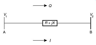
FIG. 1 Typical power flows in electric circuits.
The maximum possible active power transfer, P_max is given by ...
It’s clear from the above formula that active power transfer capacity is improved if V2 is increased.
AMAZON multi-meters discounts AMAZON oscilloscope discountsSeries capacitors
Series capacitors are utilized to neutralize part of the inductive reactance of a power network. From the phasor diagram we can see that the load voltage is higher when the capacitor is inserted in the circuit.
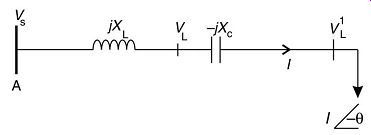
FIG. 2 Use of series capacitors to neutralize inductor reactors
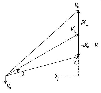
FIG. 3 Phasor diagram with series capacitor in circuit
Introducing series capacitance in the network reduces the net reactance X, and increases the load voltage, with the result that the circuit's transmission capacity is increased, as can be seen from equation. Series capacitors have the following benefits to the network:
• Improved voltage conditions
• Enhanced stability performance
• Controlling reactive power balances
• Aid in load distribution and control of overall transmission losses.
Due to the added transmission capacity, series-capacitor compensation may delay investments in additional overhead lines and transmission equipment, which can have capital investment benefits to the utility company as well as environmental impact advantages.
The first series-capacitor installation in the world was a 33 kV, 1.25 MVAr capacitor bank on the New York Power and Light system in 1928. Many higher-rated systems have since been installed all over the world.
AMAZON multi-meters discounts AMAZON oscilloscope discountsReducing the net reactance in a system has another direct consequence, which must be taken into account. What is it and what care should be taken?

The installation of series-capacitance in an AC transmission system can result in the phenomenon of subsynchronous resonance (SSR), due to the interaction between the compensated electrical system (in electrical resonance) and a turbine-generator mechanical system (in mechanical resonance). Energy is then exchanged between the electrical and mechanical systems at one or more natural frequencies of the combined system below the synchronous frequency of the system. Increasing mechanical oscillations can occur resulting in eventual mechanical failure of the turbine-generator system.
The following are techniques to counteract SSR:
• Supplementary excitation control: The subsynchronous current and/or voltage is detected and the excitation current is modulated using high-gain feedback to vary the generator output voltage, which counters the subsynchronous oscillations.
• Static filters: These are tuned to correspond to the power system frequency to filter out the oscillation mode frequencies. They are normally connected in series with each phase of the generator(s).
• Dynamic filters: In a manner similar to that of excitation control, the subsynchronous oscillations are detected, a counter emf is generated and injected into the power network through a series transformer to neutralize the unwanted oscillations.
• Bypassing series capacitors: To limit transient torque build-up.
• Amortisseur windings on the pole faces of the generator rotors can be employed to improve damping.
• A passive SSR countermeasure scheme involves using three different combinations of inductive and capacitive elements on the three phases. The combinations will have the required equal degree of capacitive compensation in the three phases at the power frequency. At any other frequency, the three combinations will appear as unequal reactance in the three phases. In this manner, asynchronous oscillations will drive unsymmetrical three-phase currents in the generator's armature windings. This creates an mmf with a circular component of a lower magnitude, compared with the corresponding if the currents were symmetrical. The developed interacting electromagnetic torque will be lower.
The following points are worth noting when considering the merits of series capacitors:
• Series capacitors are very effective when the total line reactance is high.
• Series capacitors are effective to compensate for voltage drop and voltage fluctuations.
• Series capacitors are of little value when the reactive power requirements of the load are small.
• In cases where thermal considerations limit the line current, series capacitors are of little value since the reduction in line current associated with them is relatively small.
In the last two points mentioned above, shunt capacitors may be considered instead of series capacitors.

Shunt capacitors
Shunt capacitors supply capacitive reactive power to the system at the point where they are connected, mainly to counteract the out-of-phase component of current required by an inductive load. They may either be energized continuously or switched on and off during load cycles.
FIG. 4 illustrates a circuit with shunt capacitor compensation applied at the load side.
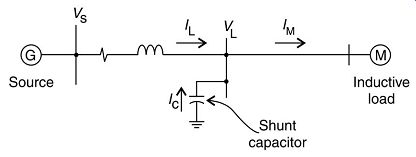
FIG. 4 Use of shunt capacitors to counteract out-of-phase current component
Referring to the phasor diagram, the line current IL is the sum of the motor
load current IM and the capacitor current IC.
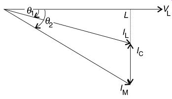
FIG. 5 Current phasor diagram: It can be seen that the line current is decreased
by adding the shunt capacitor. The angle between the load voltage and current
is decreased from f2 to f1.
FIG. 6 displays the corresponding voltage phasors. The result of adding the shunt capacitance is to decrease the source voltage from Vs1 to Vs2.
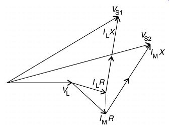
FIG. 6 Voltage phasor diagram: It can be seen from the above that the application
of shunt capacitors in a network with a lagging power factor has the following
benefits:
• Increase voltage level at the load
• Improve voltage regulation (if the capacitors are switched in and out of the network correctly)
• Reduce I^2 R active power loss and I^2 X reactive power loss due to the reduction in current
• Increase power factor
• Decrease kVA (or mVA) loading on the source generators and network to relieve an overload condition or make capacity available for additional load growth
• Reduce demand kVA where power is purchased
• Reduce investment in system facilities per kW of load supplied.
A capacitor starting system may be employed to reduce high inrush currents with the starting of large motors. This aids in maintaining the voltage level in the system. The high inductive component of the starting current is reduced by the addition of capacitance during the starting period only. In this, it differs from applying capacitors for power factor correction.
Note that in determining the amount of shunt capacitance required, some additional capacitive kVAr above that based on initial conditions without capacitors may be required. This is due to the fact that a voltage rise increases the lagging kVAr in the exciting currents of transformers and motors.
Caution:
Increased harmonics on the power system and/or a harmonic resonance condition may result with applying capacitors, especially when using harmonic-generating apparatus, such as thyristor controllers. Either a shunt or series resonance condition, or a combination of both, may occur if the resonant point happens to be close to one of the frequencies generated by harmonic sources in the system.
This can result in excessive harmonic currents flowing or harmonic overvoltages, or both, causing possible operation of the capacitor protection equipment (such as fuses), capacitor failure, overheating of other electrical equipment and electrical system interference.
| Top of Page | PREV: Low-voltage PVC- and XLPE-insulated 600/1000 V power cables | NEXT: Compensation -- part 2 | Index |