AMAZON multi-meters discounts AMAZON oscilloscope discounts
Transformers are important in any distribution system and it’s essential that they provide continuous service and are protected against faults that may keep out of service for long durations. Before proceeding with the protection methods, following paragraphs highlight the properties of transformers which shall be kept in mind while designing the protective system.
AMAZON multi-meters discounts AMAZON oscilloscope discountsTransformer magnetizing characteristics:
For efficiency reasons transformers are generally operated near to the 'knee-point' of the magnetic characteristic. Any increase above the rated terminal voltage tends to cause core saturation and therefore demands an excessive increase in magnetization current.
When a transformer is energized, it follows the classic magnetization curve.
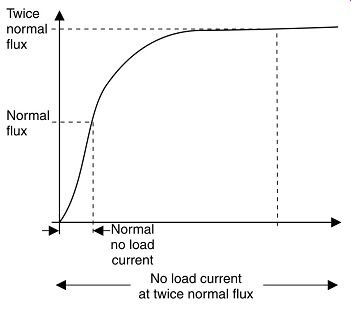
FIG. 35. Transformer magnetizing characteristics.
In-rush current:
Under normal steady-state conditions, the magnetizing current, I, required to produce the necessary flux is relatively small, usually less than 1% of full load current:
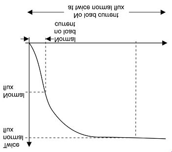
FIG. 36. Steady-state conditions.
However, if the transformer is energized at a voltage zero then the flux demand during the first half voltage cycle can be as high as twice the normal maximum flux. This causes an excessive unidirectional current to flow, referred to as the magnetizing in-rush current as shown.
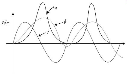
FIG. 37. Magnetizing in-rush current.
An analysis of this waveform will show that it contains a high proportion of second harmonic and will last for several cycles. Residual flux can increase the current still further, the peak value attained being of the order of 2.8 times the normal value if there is 80% permanence present at switch-on.
As the magnetizing characteristic is non-linear, the envelope of this transient in-rush current is not strictly exponential. In some cases, it has been observed to be still changing up to 30 min after switching on.
It’s therefore important to be aware of these transient phenomena when considering differential protection of transformers, which will be discussed later.
AMAZON multi-meters discounts AMAZON oscilloscope discounts
FIG. 38. Typical transient current-rush when switching in a transformer at
instant when E = 0
Mismatch of current transformers:
Current transformers are provided on the HV and LV sides of a power transformer for protection purposes.
If we consider a nominal 132/11 kV 10 MVA transformer, the HV and LV full load currents would be as follows. A ratio of 50/1 A would most likely be chosen for the HV current transformers, as it’s not possible to obtain fractions of a turn. A ratio of 500/1 could be achieved comfortably for the LV current transformers.
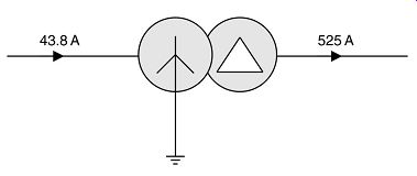
FIG. 39. Nominal 132/11 kV 10 MVA transformer.
We therefore have a mismatch of current transformer ratios with respect to the full load currents on the secondary side of the CTs (these are 0.876 A and 1.05 A). Incidentally 600/1 on the secondary side would be more suitable.
Furthermore, it’s more than likely that the HV CTs and the LV CTs will be supplied by different manufacturers. There is therefore no guarantee that the magnetization curves will be the same, which will further add to the mismatch. This mismatch shall be duly considered while selecting the settings for the relays protecting the transformers.

Types of faults:
A clear knowledge is required to understand the different types of faults that can occur in a transformer and their causes. This will enable the designer to adopt the correct protective system depending upon the possibilities for such faults, cost of protection vis-à-vis breakdown cost, etc. The following paragraphs briefly explain the descriptions for the following types of faults that can occur in a power transformer:
- • HV and LV bushing flashovers (external to the tank)
- • HV winding ground fault
- • LV winding ground fault
- • Inter-turn fault
- • Core fault
- • Tank fault
Phase-to-phase faults within the tank of a transformer are relatively rare by virtue of its construction. They are more likely to occur external to the tank on the HV and LV bushings.
If a transformer develops a winding fault, the level of fault current will be dictated by:
- • Source impedance
- • Method of neutral grounding
- • Leakage reactance
- • Position of fault in winding (i.e. fault voltage).
Earth faults:
Effectively grounded neutral:
This refers to the solid connection of neutral to the ground. The fault current in this case is controlled mainly by the transformer leakage reactance, which varies in a complex manner depending on the position of the fault in the winding.
The reactance decreases toward the neutral so that the current actually rises for faults toward the neutral end.
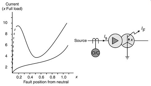
FIG. 40. Relationship of fault current to position from neutral (earthed).
The input primary current is modified by the transformation ratio and is limited to 2 to 3 times the full load current of the transformer for fault positions over a major part of the star winding.
An overcurrent relay on the HV side will therefore not provide adequate protection for ground faults on the LV side.
Non-effectively (resistance or impedance) grounded neutral For this application, the fault current varies linearly with the fault position, as the resistor is the dominant impedance, limiting the maximum fault current to approximately full load current.
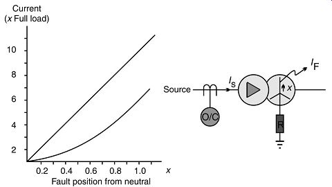
FIG. 41. Relationship of fault current to positions from neutral (resistance
grounded)
The input primary current is approximately 57% of the rated current making it impossible for the HV overcurrent relay to provide any protection for LV ground faults.
Restricted ground fault protection is therefore strongly recommended to cover winding ground faults and this will be covered in more detail in a later section.
Inter-turn faults
Insulation between turns can break down due to electro-magnetic/mechanical forces on the winding causing chafing or cracking. Ingress of moisture into the oil can also be a contributing factor.
Also an HV power transformer connected to an overhead line transmission system will be subjected to lightning surges sometimes several times rated system voltage. These steep-fronted surges will hit the end windings and may possibly puncture the insulation leading to a short-circuited turn. Very high currents flow in the shorted turn for a relatively small current flowing in the line.
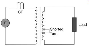
FIG. 42. Inter-turn faults.
Core faults:
Heavy fault currents can cause the core laminations to move, chafe and possibly bridge causing eddy currents to flow, which can then generate serious overheating.
This additional core loss won’t produce any noticeable change in the line currents and thus cannot be detected by any electrical protection system.
Power frequency overvoltage not only increases stress on the insulation but also gives an excessive increase in magnetization current. This flux is diverted from the highly saturated laminated core into the core bolts, which normally carry very little flux. These bolts may be rapidly heated to a temperature, which destroys their own insulation, consequently shorting out core laminations.
Fortunately, the intense localized heat, which will damage the winding insulation, will also cause the oil to break down into gas. This gas will rise to the conservator and be detected by the Buchholz relay, which is an external device provided in oil-filled transformers rated above 1000 kVA.
Tank faults:
Loss of oil through a leak in the tank can cause a reduction of insulation and possibly overheating on normal load due to the loss of effective cooling.
Oil sludge can also block cooling ducts and pipes, contributing to overheating, as can the loss of forced cooling pumps and fans generally fitted to the larger transformer.
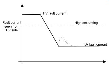
FIG. 43. Fault current as seen from the HV side.
| Top of Page | PREV: Transformer construction / installation | NEXT: Transformer Protection Relays | Index |