by Dave Goodman
* Low Cost, Short Range, Heat/Movement Detector.
* Ideal for Doorways, Stairs and Proximity Systems.
* Low Power Consumption for Long Battery Life.
Commercially available body heat, movement detection systems, although very sophisticated in their operation, can be rather expensive for use in limited applications where short range coverage is required. This UR proximity detector has been designed as a simple low cost system for detecting heat changes, movement of a warm body, etc., such as those emitted from the human body. The unit responds to a definite change or disturbance in ambient -- or background -- heat levels and could be placed across a doorway or stairs to indicate movement in those areas.
Pyroelectrics
The F001P sensor uses a ceramic, ferroelectric element made from Lead Zirconate Titanate (PZT), which has the property of producing an electrical change at its surface when the tempera ture changes, due to a change in polarization intensity. If a moving object enters the field of view of this sensor, changes in infra red energy levels occur due to a difference in temperature between this object and the background.
Infra red energy is converted into heat by the surface electrode of the element, thus causing a change in temperature within the element itself, and a small electric charge is created as a result (see Figure 1).
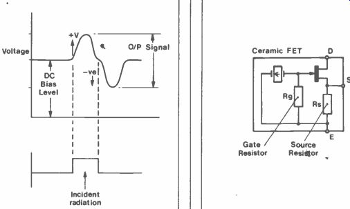
This small charge appears across the gate resistance Rg in Figure 2, and is impedance buffered by the FET source follower, where a change in voltage appears across source resistance Rs. A small DC bias voltage (IDRs) is produced by the quiescent current (ID) flowing through the FET while no signal is present, as Figure 3, and output signals from the source terminal overlap this level with a +Ve voltage swing.
In use, the voltage swing is very small, its amplitude being determined by the amount of incident energy available, which becomes smaller with increasing distance.
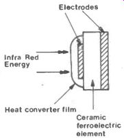
Figure 1. Pyroelectric Element.
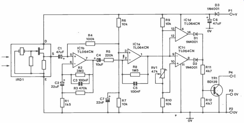
Figure 2. Sensor Circuit.
Done with Mirrors!
A negligible amount of energy is emitted from the human body which limits the effective working range of the module down to four feet or so. This range could be extended by increasing the sensitivity of the amplifier and developing velocity related filter circuits which would determine a given range of movement speeds and size of body.
An even more effective method is employed on commercial systems, in the form of collecting lenses and optical amplifying concave mirrors. Problems associated with energy collecting systems are: movements in the air, sunlight 'modulated' through curtains and even small animals generating fluctuations in the infra red energy background. To help overcome these sorts of problems, a multi -faceted, concave mirror is often used, which has the effect of expanding (or narrowing) the field of view into bands.
As an infra red emitting source crosses the field of view, radiated energy bounces off these facets in a sequence.
The sensor responds with a series of related output pulses, and detection electronics can determine the size, velocity and direction of the source while it is moving. Quite a sophisticated achievement, and such a system is available in our catalog, being more suitable for security and alarm uses than this particular system. However, many applications exist where a simpler system is called for, especially for the home constructor!
Circuit Description
Figure
3. Source Output Voltage Swing. Figure 4. Proximity detector Circuit.
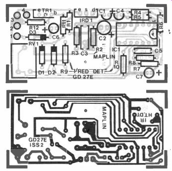
Figure 5. PCB Artwork.
The circuit, shown in Figure 4, consists of two amplifying stages, with low pass filtering and a comparator threshold stage. Output voltage swings from the IRD are amplified by IC1b, which is configured as a noninverting amplifier. The IRD receives energy from many sources, and a mixed waveform would be produced at IC1b output, therefore C3 integrates continuous low level signals and acts as a low pass filter.
The somewhat unusual arrangement of resistors RI and R4 allow C2 to charge slowly during initial power up. C2 is necessary for isolating IClb -Ve input from the OV supply rail. With single supply op -amps, it is common to generate a half supply DC voltage reference to bias the differential inputs, thus allowing output voltage swings about this level. The effect of integration on the continuous input signals produces a very low frequency output signal, which is applied to C2.
The charge across C2 varies with the magnitude of the output signal (from pin 7), and limits heavy transients from saturating this stage.
ICla is a standard inverting amplifier, again voltage referenced to half supply by R6 and R7. C7 decouples the reference voltage to prevent comparator supply spikes from being introduced into the stage. ICld and IC1c serve as a simple comparator. The threshold voltage reference, determining when the comparators will trigger, is set by RV1 in the potential divider chain R9 and R10.
Positive voltage swings from ICla trigger the ICld comparator causing DI to conduct, while negative swings trigger IC1c causing D2 to conduct. From Figure 3 it can be seen that the output voltage swing from the IRD is, firstly, in a positive direction and then secondly in a negative direction. The ultimate effect from the comparator output at R11 is therefore not one but two pulses turning on transistor TR1.
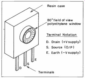
Figure 6. Sensor pin-outs.
Either one of diodes D1 or D2 could be removed for single pulse output and which particular one to remove must be decided under full operational conditions. TR1 is an open collector switch, and will sink external loads (sourced from their own external +V supply) to the OV common rail when conducting.
Construction For information on building details and components, refer to Figure 5 for the board layout and to the 'Constructor's Guide' supplied with this kit (if you do not intend to purchase the complete kit then see the Parts List for the order code of the Constructor's Guide, price 25p).
Identify and insert resistors R1 to R12.
Solder these components and remove excess wire before continuing.
Mount diodes D1 to D3, and insert veropins at Pin 1 to Pin 4 in the holes marked with white circles. Next, insert a 14 -pin IC socket in position IC1, and bend a few legs over the track pads to hold it in position. The PCB is quite small with tracks running close together, so care must be taken whilst soldering, as short circuits between tracks can easily occur.
Identify and insert capacitors C1 to C7. Poly-layer type C3 should be fitted carefully to prevent breaking the lead out wires from each end of the package. Fit preset RV1, and solder all components in position. Again, cut off all excess leads, then fit TR1 and the sensor IRD1 shown in Figure 6. One side of TR1 has a metal, heat transfer mounting plate fitted. Insert TR1 with this plate facing outward towards the edge of the pcb. The sensor IRD1, shown in Figure 7, could be mounted vertically from the pcb, or horizontally off the pcb as detailed.
Mount the sensor as close as possible - in both cases - to the pcb in order to reduce noise induced into this area.
Either mounting position will have to take into account the boxing (case) requirements, and this is left to the fitting as required by the constructor. Solder any remaining components, cut off all excess wires and clean up the track area to facilitate inspection.
----------
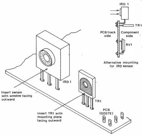
Figure 7. Mounting arrangements.
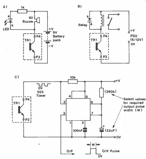
Figure 8. External Circuit Connections.
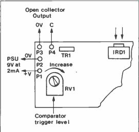
Figure 9. External PCB Connections.
Testing
Supply requirements for the module are 9V DC @ 2mA. Current consumption is low, which allows long periods of use from small battery packs such as the PP3.
Connect the battery +Ve to Pin 1, and -Ve to Pin 2; diode D3 prevents damage to components in the event of accident ally reversed battery polarities.
Check the supply current with an milliammeter, which will be around 2.5mA for a minute or so, dropping to 1 - 1.5mA after this period. Current consumption increases by approximately 1 mA while the comparator stages are operating.
The output transistor TR1 does not source current, but being open collector will sink current from an external supply load. Figure 8 suggests various methods of switching external loads, and diagram (a) could be used for testing purposes.
Connect the LED cathode (k) to collector Pin 4, and wire the battery to one end of a 1 k-o resistor connected to the LED anode (a).
If using the same battery for both module supply and LED supply, then the second battery -Ve connection is not required. Turn the comparator threshold control, RV1, to half travel (Figure 9), and after the initial 'warming up' period, move your hand across the sensor window. Do not poke the window with fingers as grease deposited will reduce sensitivity and may prevent operation completely! Figure 10 shows the spectral response expected in the window. The LED will light for a few seconds. If the LED is permanently aglow, turn the trigger level down by moving RV1 wiper anti-clock wise.
Using the Module TR1 is not capable of switching heavy loads and should be used on external systems up to 12V DC, and current levels below 100mA. Relays could be used for controlling larger voltage/current devices (Figure 8b), or a timer could be employed to generate long operating periods once triggered (Figure 8c). On the prototype, a 6V @ 35mA buzzer was used, on a separate supply, to good effect. Any battery supplying the electronics should not be used for supplying the external devices as well, if more than a simple LED arrangement is to be used. Battery connections to Pin 1 and 2 should be kept short--a PP3 clip lead is ideal for this --and mount both module and battery together in the same housing with a suitable ON/OFF switch.
Sensing range is 4 to 5 feet, depending upon the sensor's field of view and variations in the light/heat background levels. A whole room, for instance, could not adequately be covered by this system, but doorways, narrow hallways and corridors are suitable areas. Another use for the module could be in a shower cubicle, using a timer circuit for controlling the water pump. Obviously, low voltage switching systems are important in this application.
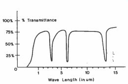
Figure 10. Window Spectral response.
==============
INFRA RED PROXIMITY DETECTOR
PARTS LIST
RESISTORS: All RI 1k5 1 (M1K5) R2 3M3 1 (M3M3) R3 470k 1 (M470K) R4 100k (M10010 R6 220k 1 (M2201) R8,7,9,10 10k 4 (MIOK) R8 IM5 1 (M1M5) RI 1,12 RV1 4k7 47k Hor. Sub -min Preset 2 1 worn (WR60Q)
CAPACITORS C1,6 C2,7 C3 C4 47p! 16V Minelect 22pF 16V Minelect 100nF Polyester 10µF 16V Minelect 2 2 1 1 (YYsib) (YY36P) (WW41U) (YY34M) C5 100nF Min disc 1 (YR75S)
A complete kit of all parts is available for this project:
Order As LM13P (I/R Detector Kit) Price £10.95 The following items in the above kit list are also available separately, but are not shown in the 1986 catalogue:
I/R Detector PCB Order As GD27E Price £1.95 I/R Detector FOO1P Order As FD13P Price £5.95 Constructor's Guide Order As XH79L 25p NV